How To use House Electrical Plan Software


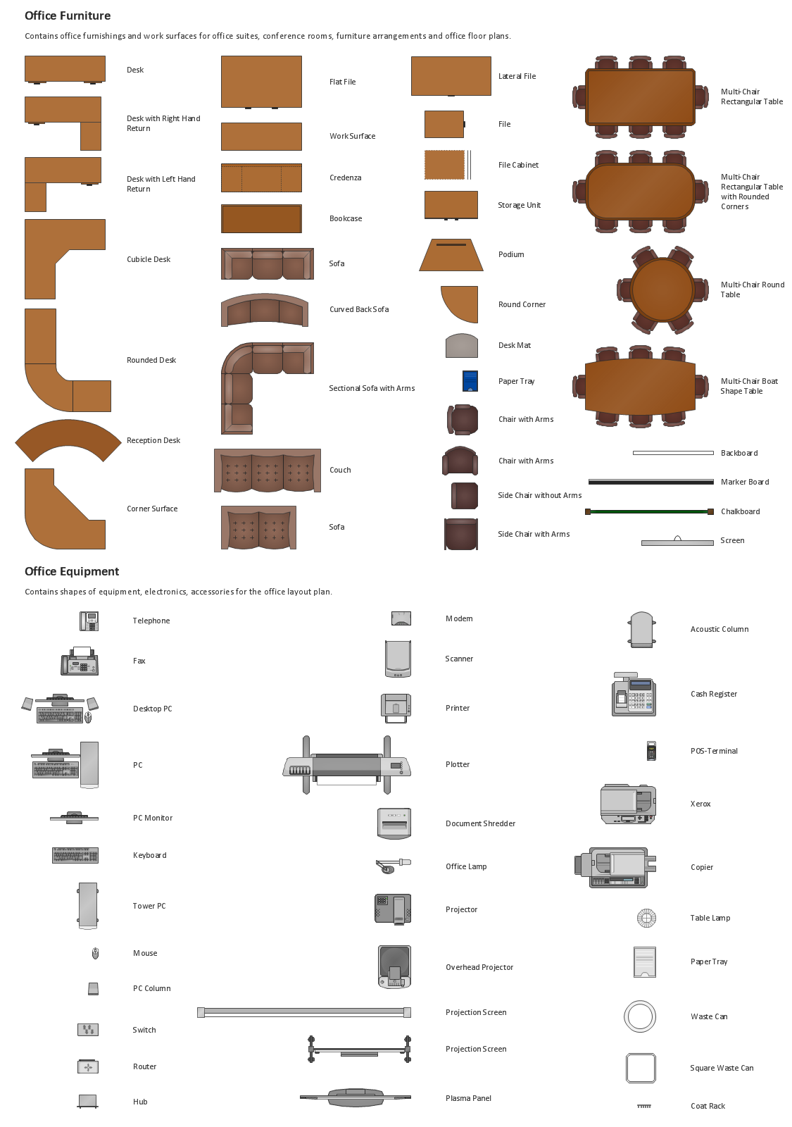
Building Drawing Design Element: Office Layout Plan

The vector stencils library "Telecommunication networks" contains 32 clipart images of telecommunication network devices and equipment for drawing telecom network diagrams.
"A telecommunications network is a collection of terminal nodes, links and any intermediate nodes which are connected so as to enable telecommunication between the terminals.
The transmission links connect the nodes together. The nodes use circuit switching, message switching or packet switching to pass the signal through the correct links and nodes to reach the correct destination terminal.
Each terminal in the network usually has a unique address so messages or connections can be routed to the correct recipients. The collection of addresses in the network is called the address space." [Telecommunications network. Wikipedia]
The clip art example "Telecommunication networks - Vector stencils library" was created using the ConceptDraw PRO diagramming and vector drawing software extended with the Telecommunication Network Diagrams solution from the Computer and Networks area of ConceptDraw Solution Park.
Internet

Globe

Base station

Satellite dish

Satellite dish

Communications satellite

Wireless cell tower

Radio waves

Radio waves

Cellular phone

Server

Laptop computer

Desktop computer

Car

Satellite truck

House

House

Office building

Mountain

Tree

Tree

User

Call-center

Multi-storey

Antenna

Router

IP phone

Fax

Network cell

IP Camera

Wireless router

Networking device

Hotel Network Topology Diagram


- Drawing Of 3d For Cellphone Tower
- 2d Cellphone Tower Drawing
- Drawing Of 2d Of A Cellphone Tower
- Advantages Of 3d Cellphone Tower
- Sketch Of A Cellphone Tower
- Oblique Drawing Of A Cell Phone Tower
- Drawing For The Cell Phone Tower In 2d
- Telephone Tower Drawing
- Flow Diagram Of Making Cell Phone Tower
- Draw A Flow Chart For Making A Cellphone Tower