UML Deployment Diagram. Design Elements

Total Quality Management Value

UML Deployment Diagram. Diagramming Software for Design UML Diagrams


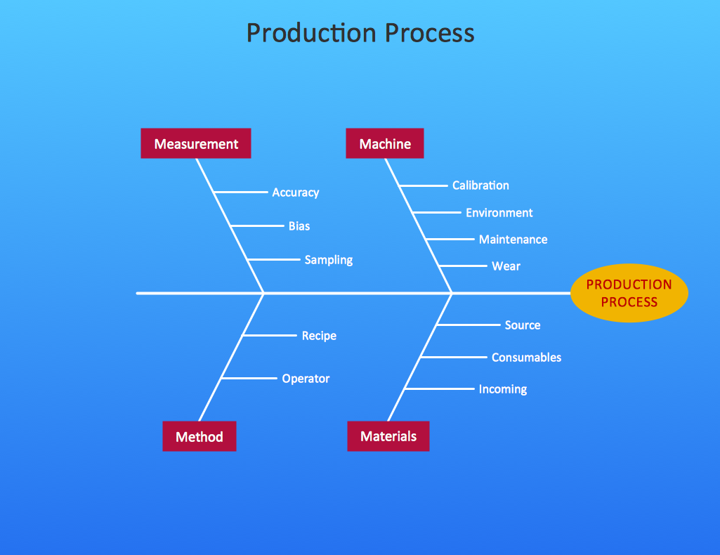
Cause and Effect Diagram
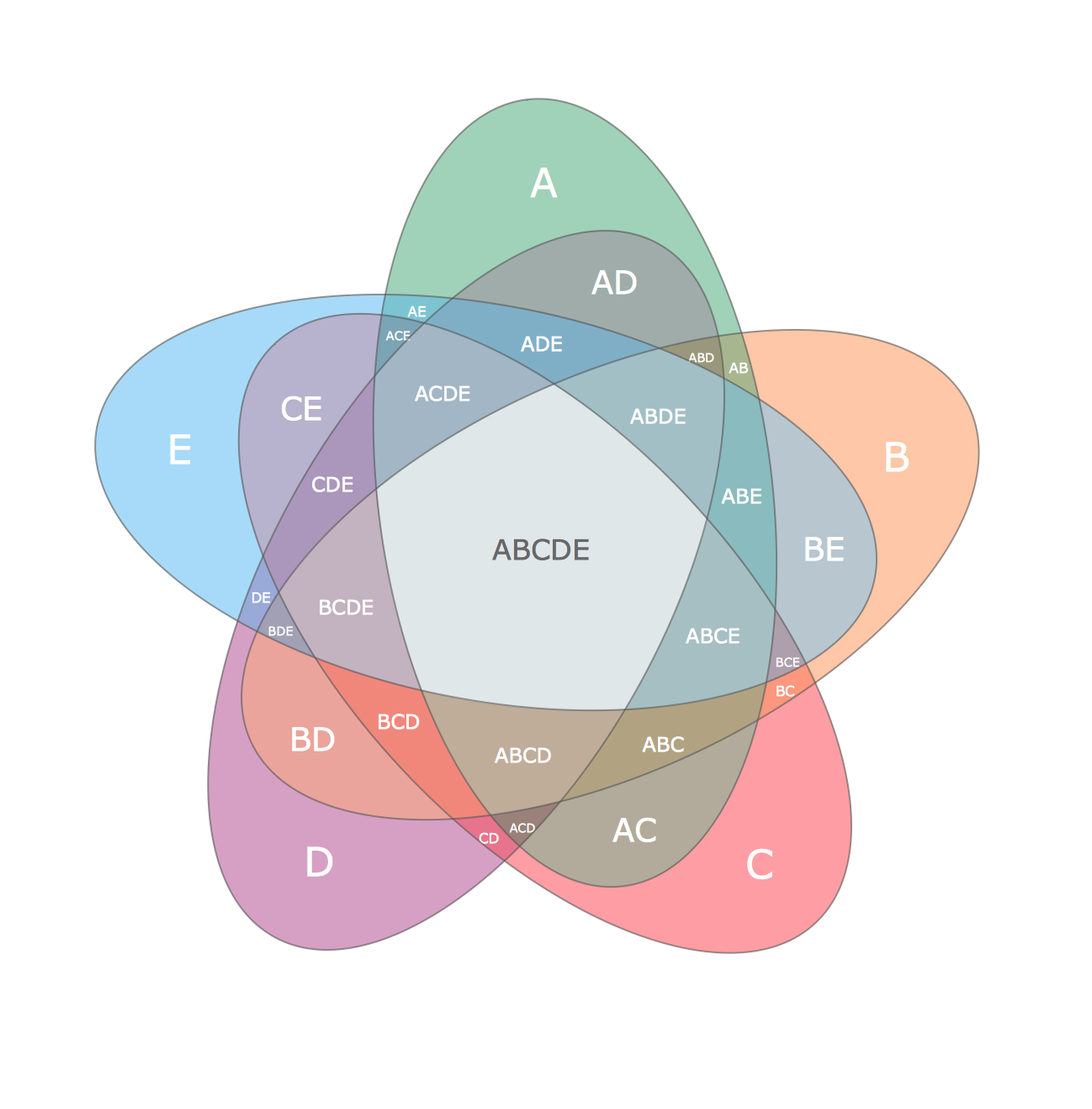
Multi Layer Venn Diagram. Venn Diagram Example
Cause and Effect Diagram Software

Diagramming Software for Design UML Interaction Overview Diagrams

Diagramming Software for Design UML Object Diagrams

Fishbone Diagram Example

Fishbone Diagram Procedure

Venn Diagrams

Fishbone Diagram Design Element
.png)
Network Topologies


UML Sequence Diagram. Design Elements

UML Sequence Diagram

- Draw The Diagram Of Business Environment
- Draw A Diagram Of Business Environment That Shows All The
- Draw A Diagram Of Business Environment That Shows System
- Drawing A Diagram Of Business Environment That Show All The
- Diagram Of Business Environment That Shows All The Elements
- Draw A Diagram Of Business Enviroment That Shows All The Element
- Diagram Of Business Environment That Show All The Elements Of A
- Draw A Diagram Of Business Environment That Show All The Element
- Business Environment Drawing
- Draw Th Diagram Of Business Enironment
- Draw A Micro Software Environment
- Diagrams Of Business Environment
- Business Environment Flow Chart
- Diagram That Illustrates The Element Of Business Environment
- Business Environment Factors Flow Chart
- Draw A Diagram Of Management Environment
- A Diagram To Show Business Environment
- Simply Diagram Of Business Environment
- Process Flowchart | UML Deployment Diagram . Design Elements ...