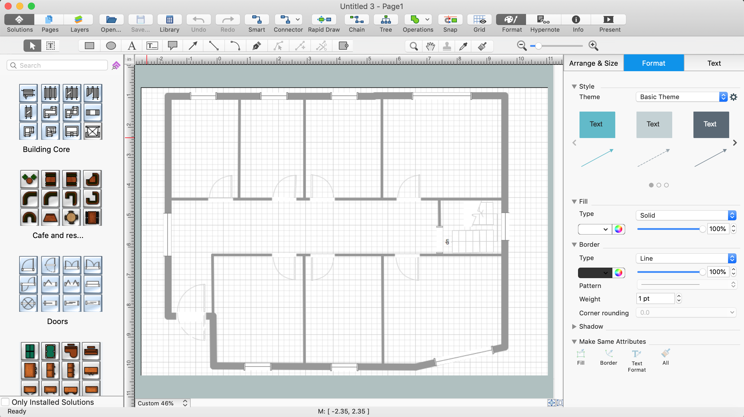
How To use House Electrical Plan Software
How we can conduct the electricity at house correctly without a plan? It is impossible. The House electrical diagram depicts locations of switches, outlets, dimmers and lights, and lets understand how you will connect them. But design of House Electrical Plan looks a complex task at a glance, which requires a lot of tools and special experience. But now all is simple with all-inclusive floor plan software - ConceptDraw PRO. As a house electrical plan software, the ConceptDraw PRO contains libraries with a large range of professional lighting and electrical symbols, ready-to-use electrical plans samples and examples, and built-in templates for creating great-looking Home floor electrical plans. It is a fastest way to draw Electrical circuit diagrams, Electrical wiring and Circuit schematics, Digital circuits, Electrical equipment, House electrical plans, Satellite television, Cable television, Home cinema, Closed-circuit television when are used the tools of Electric and Telecom Plans Solution from ConceptDraw Solution Park. Files created in Visio for Mac app can be easily imported to ConceptDraw PRO. Also you may import stencils and even libraries. Try for free an alternative to Visio that Apple users recommend.
Chemical Engineering
ConceptDraw PRO is a powerful diagramming and vector drawing software. Extended with Chemical and Process Engineering Solution from the Industrial Engineering Area of ConceptDraw Solution Park, it became the best Chemical Engineering software.CAD Software for Architectural Designs
Computer-aided design (CAD) is the use of the computer software to create drawings. Today the large quantity of the technical drawings and architectural designs is created using the CAD software. CAD software makes the design process convenient, efficient and productive. ConceptDraw PRO diagramming and vector drawing software allows you the possibility to draw your architectural designs quick, simple and effective.Use the libraries with a set of vector objects, templates and samples from the Floor Plans Solution from the Building Plans area of ConceptDraw Solution Park for designing your professional architectural designs.
 Entity-Relationship Diagram (ERD)
Entity-Relationship Diagram (ERD) solution extends ConceptDraw PRO software with templates, samples and libraries of vector stencils from drawing the ER-diagrams by Chen's and crow’s foot notations.
- Process Flowchart | Design elements - Industrial equipment ...
- Mechanical Drawing Symbols | Electrical Symbols — Rotating ...
- Process Flowchart | Process Flow Diagram Symbols | Process ...
- Mechanical Drawing Symbols | Mechanical Engineering | Process ...
- Design elements - Presentation symbols | Office - Design Elements ...
- CAD Drawing Software for Making Mechanic Diagram and Electrical ...
- Process Flowchart | Mechanical Drawing Symbols | Mechanical ...
- Mechanical Drawing Symbols | Technical Drawing Software ...
- Symbols Used In Pipeline Drawing
- Mechanical Drawing Symbols | Design elements - Dimensioning ...
- Process Chart Symbols Industrial Engg
- Symbols On Pressure Vessel
- Mechanical Drawing Symbols | Basic Flowchart Symbols and ...
- Piping and Instrumentation Diagram Software | Mechanical Drawing ...
- Mechanical Drawing Symbols | Design elements - Bearings ...
- Internet symbols - Vector stencils library | Data Flow Diagram ...
- Some Industrial Symbols Of Electrical Equipments Of The Building ...
- Technical Drawing Software | Electrical Drawing Software and ...
- Basic Flowchart Symbols and Meaning | Business Process ...
- Mechanical Drawing Symbols | Engineering | Process Flowchart ...


