UML Deployment Diagram Example - ATM System UML diagrams

UML Use Case Diagram Example. Services UML Diagram. ATM system

Communication Diagram UML2.0 / Collaboration UML1.x


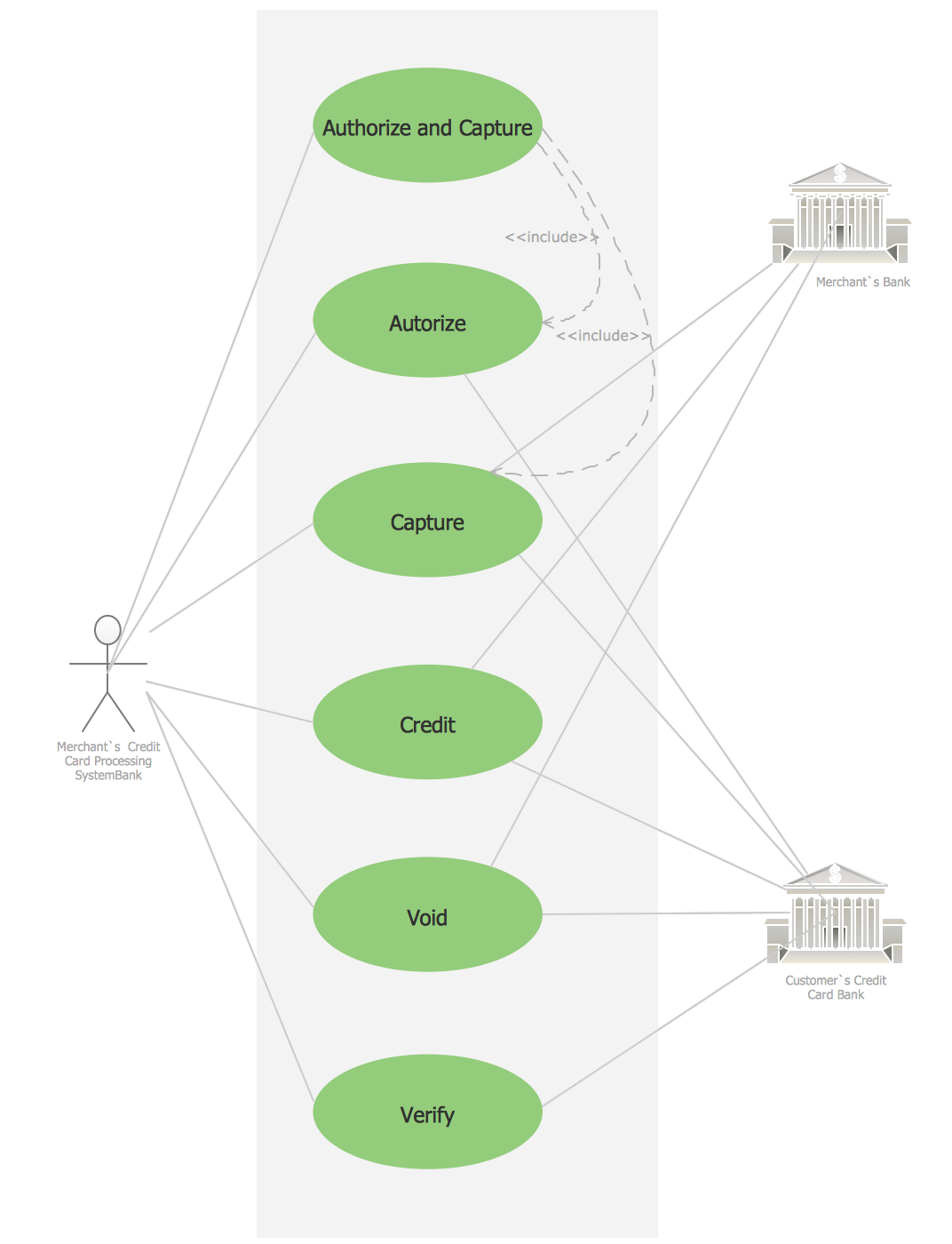
Credit Card Processing System UML Diagram
UML Use Case Diagrams

Create UML Diagram
UML for Bank

Diagramming Software for Design UML Collaboration Diagrams

 Fishbone Diagram
Fishbone Diagrams solution extends ConceptDraw DIAGRAM software with templates, samples and library of vector stencils for drawing the Ishikawa diagrams for cause and effect analysis.
UML Diagram

 Active Directory Diagrams
Active Directory Diagrams solution significantly extends the capabilities of ConceptDraw DIAGRAM software with special Active Directory samples, convenient template and libraries of Active Directory vector stencils, common icons of sites and services, icons of LDPA elements, which were developed to help you in planning and modelling network structures and network topologies, in designing excellently looking Active Directory diagrams, Active Directory Structure diagrams, and Active Directory Services diagram, which are perfect way to visualize detailed structures of Microsoft Windows networks, Active Directory Domain topology, Active Directory Site topology, Organizational Units (OU), and Exchange Server organization.
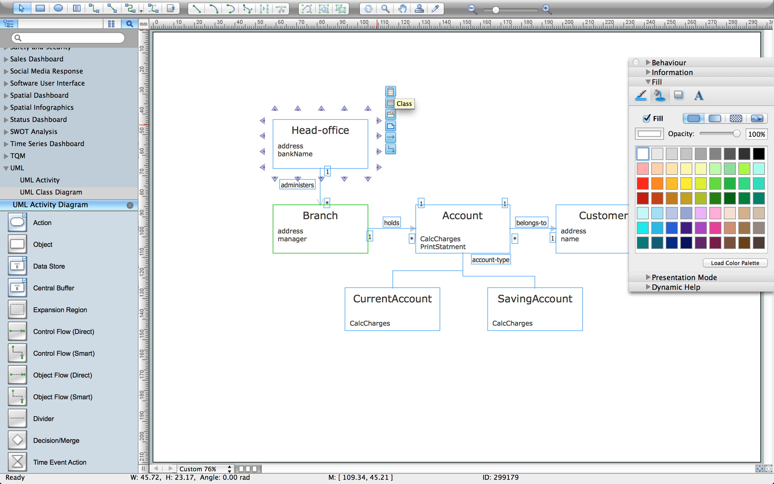
UML Class Diagram. Design Elements

 Interactive Voice Response Diagrams
Interactive Voice Response Diagrams solution extends ConceptDraw DIAGRAM software with samples, templates and libraries of ready-to-use vector stencils that help create Interactive Voice Response (IVR) diagrams illustrating in details a work of interactive voice response system, the IVR system’s logical and physical structure, Voice-over-Internet Protocol (VoIP) diagrams, and Action VoIP diagrams with representing voice actions on them, to visualize how the computers interact with callers through voice recognition and dual-tone multi-frequency signaling (DTMF) keypad inputs.
 Entity-Relationship Diagram (ERD)
Entity-Relationship Diagram (ERD) solution extends ConceptDraw DIAGRAM software with templates, samples and libraries of vector stencils from drawing the ER-diagrams by Chen's and crow’s foot notations.
UML Diagram Types List

- Class UML Diagram for Bank Account System | UML class diagram ...
- Collaboration Diagram In Uml For Banking On Computer
- UML use case diagram - Banking system
- Diagramming Software for Design UML Collaboration Diagrams ...
- Draw A Uml Use Class Diagram For Opening A Bank Account
- Draw A Uml Class Diagram For Opening Account
- UML use case diagram - Banking system | UML Use Case Diagram ...
- UML Deployment Diagram Example - ATM System UML diagrams ...
- UML for Bank | UML use case diagram - Banking system | UML Use ...
- Draw The Collaboration Diagram For Bank System
- Class UML Diagram for Bank Account System | UML Class ...
- UML Deployment Diagram Example - ATM System UML diagrams ...
- Collaboration Diagram For Banking System
- Class UML Diagram for Bank Account System | UML use case ...
- UML class diagram - Bank account | ATM UML Diagrams | Data ...
- UML Class Diagram Generalization Example UML Diagrams | UML ...
- UML class diagram - Bank account
- Use Case Diagram Of Banking System
- Diagramming Software for Design UML Collaboration Diagrams ...
- UML Collaboration Diagram (UML2.0) | UML Activity Diagram | State ...