 Entity-Relationship Diagram (ERD)
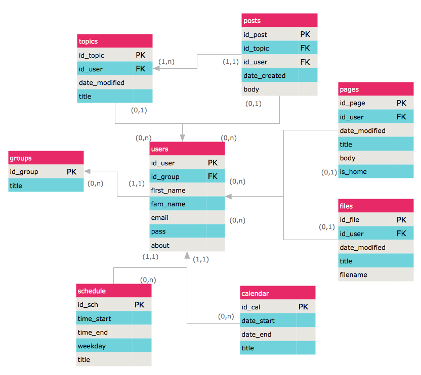
Entity-Relationship Diagram (ERD) solution extends ConceptDraw PRO software with templates, samples and libraries of vector stencils from drawing the ER-diagrams by Chen's and crow’s foot notations.
HelpDesk
How to Create an ERD Diagram
ERD (entity relationship diagram) is used to show the logical structure of databases. It represents the interrelationships between components of database (entities). Entity relationship diagrams are a widely used in software engineering. Using ERD software engineers can control the every aspect of database development. ER diagram can be used as guide for testing and communicating before the release of software product. ERD displays data as entities that are connected with connections that show the relationships between entities. There is some ERD notations used by data bases developers for representing the relationships between the data objects. ConceptDraw PRO and its ERD solution allow you to build ERD diagram of any notation.
 Fishbone Diagram
Fishbone Diagrams solution extends ConceptDraw PRO software with templates, samples and library of vector stencils for drawing the Ishikawa diagrams for cause and effect analysis.
HelpDesk
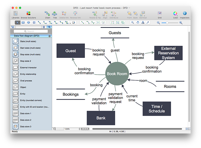
How to Create a Data Flow Diagram using ConceptDraw PRO
Data flow diagramming is a highly effective technique for showing the flow of information through a system. Data flow diagrams reveal relationships among and between the various components in a program or system. DFD is an important technique for modeling a system’s high-level detail by showing how input data is transformed to output results through a sequence of functional transformations. The set of standard symbols is used to depict how these components interact in a system. ConceptDraw PRO allows you to draw a simple and clear Data Flow Diagram using special libraries.
 Flowcharts
The Flowcharts Solution for ConceptDraw PRO v10 is a comprehensive set of examples and samples in several different color themes for professionals that need to graphically represent a process. Solution value is added by basic flow chart template and shapes' library of Flowchart notation. ConceptDraw PRO flow chart creator lets one depict a processes of any complexity and length, as well design of the flowchart either vertically or horizontally.
 Rapid UML
Rapid UML solution extends ConceptDraw PRO software with templates, samples and libraries of vector stencils for quick drawing the UML diagrams using Rapid Draw technology.
 Enterprise Architecture Diagrams
Enterprise Architecture Diagrams solution extends ConceptDraw PRO software with templates, samples and library of vector stencils for drawing the diagrams of enterprise architecture models.
 Metro Map
Metro Map solution extends ConceptDraw PRO software with templates, samples and library of vector stencils for drawing the metro maps, route maps, bus and other transport schemes, or design tube-style infographics.
- Entity Relationship Diagram Examples
- Er Diagram For Library Data
- Design elements - ERD (crow's foot notation) | Entity Relationship ...
- Library Management For Dfd Erd Diagram In Document
- Erd Diagram For Library Management For Word File
- DFD Library System | Data Flow Diagram Symbols. DFD Library ...
- Library Management System Er Diagram And Dfd
- Draw Data Flow Diagram For Library Management System
- Data Flow Diagrams | DFD Library - Design elements | How to ...
- Data Flow Diagram Symbols. DFD Library | Entity Relationship ...
- Dfd And Er Diagram Of Library Management System
- Er Diagram For Library Management System Crows Foot Notation
- DFD Library System | Data Flow Diagrams (DFD) | Example of DFD ...
- Library Erd Diagram
- Draw The Er Diagran Of Library
- Entity Relationship Diagram For Libaray Management
- System Modeling For Library Data Flow Diagram Sample
- Data Flow Diagrams | Entity-Relationship Diagram (ERD) | Process ...
- Data Flow Diagrams | Entity-Relationship Diagram (ERD) | Software ...
- Data Flow Diagram Model

