 Electrical Engineering
This solution extends ConceptDraw PRO v.9.5 (or later) with electrical engineering samples, electrical schematic symbols, electrical diagram symbols, templates and libraries of design elements, to help you design electrical schematics, digital and analog
 Engineering
This solution extends ConceptDraw PRO v9.4 with the ability to visualize industrial systems in electronics, electrical, chemical, process, and mechanical engineering.
HelpDesk
How to Create an Electrical Diagram Using ConceptDraw PRO
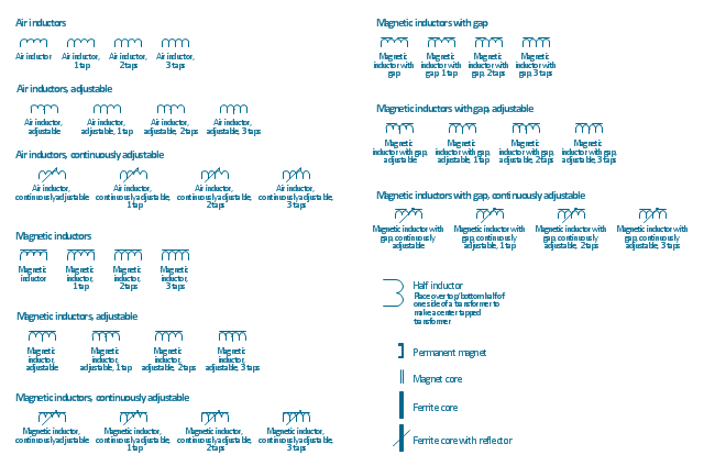
There are many of different electric circuit symbols that can be used in a circuit diagram. Knowing how to read circuit diagrams is a useful skill not only for professionals, but for any person who can start creating his own small home electronic projects. The circuit diagram shows the scheme of a location of components and connections of the electrical circuit using a set of standard symbols. It can be use for graphical documentation of an electrical circuit components. The ability to create electrical diagrams and schematic using ConceptDraw PRO is delivered by the Electrical Engineering solution. The solution supplied with samples, templates and libraries of design elements for drawing electrical schematics, digital and analog logic, circuit and wiring schematics and diagrams, power systems diagrams, maintenance and repair diagrams for electronics and electrical engineering.The vector stencils library "Inductors" contains 41 symbols of inductor elements for drawing electronic circuit diagrams.
"An inductor, also called a coil or reactor, is a passive two-terminal electrical component which resists changes in electric current passing through it. It consists of a conductor such as a wire, usually wound into a coil. When a current flows through it, energy is stored temporarily in a magnetic field in the coil. When the current flowing through an inductor changes, the time-varying magnetic field induces a voltage in the conductor, according to Faraday’s law of electromagnetic induction, which opposes the change in current that created it.
An inductor is characterized by its inductance, the ratio of the voltage to the rate of change of current, which has units of henries (H). Inductors have values that typically range from 1 µH (10-6H) to 1 H. Many inductors have a magnetic core made of iron or ferrite inside the coil, which serves to increase the magnetic field and thus the inductance. Along with capacitors and resistors, inductors are one of the three passive linear circuit elements that make up electric circuits. Inductors are widely used in alternating current (AC) electronic equipment, particularly in radio equipment. They are used to block the flow of AC current while allowing DC to pass; inductors designed for this purpose are called chokes. They are also used in electronic filters to separate signals of different frequencies, and in combination with capacitors to make tuned circuits, used to tune radio and TV receivers." [Inductor. Wikipedia]
The symbols example "Design elements - Inductors" was drawn using the ConceptDraw PRO diagramming and vector drawing software extended with the Electrical Engineering solution from the Engineering area of ConceptDraw Solution Park.
- How To use House Electrical Plan Software | Electrical Drawing ...
- Draw And Explain And Construct Electronic Circuit Using Dtl
- Design elements - Electrical circuits | How To use House Electrical ...
- Electrical Symbols, Electrical Diagram Symbols | Design elements ...
- Easy Drawing Electronic Circuits
- Design elements - Electrical circuits | Design elements - Electrical ...
- Electrical Drawing Software | Circuits and Logic Diagram Software ...
- Design elements - Electrical circuits | Design elements - Resistors ...
- Bipolar current mirror - Circuit diagram | Amplifier - Circuit diagram ...
- Circuits and Logic Diagram Software | Electrical Drawing Software ...
- How to Create an Electrical Diagram Using ConceptDraw PRO ...
- Electrical Drawing Software | Electrical Diagram Software | Electrical ...
- Electrical Circuit Drawing Software For Mac
- Electrical Drawing Software and Electrical Symbols | Timing diagram ...
- Electrical Drawing Software | Engineering | Circuits and Logic ...
- Design elements - Inductors | Design elements - Electrical circuits ...
- Free Electronic Circuit Diagram Drawing Software
- How To use House Electrical Plan Software | Electrical Drawing ...
- How To use House Electrical Plan Software | Electrical Drawing ...
- Draw The Electronic Circuit Schematics On Computer Aided Design

