ConceptDraw DIAGRAM ER Diagram Tool
Entity-relationship model, also called ER-model, is the main tool of domain modeling on the stage of conceptual design. The modeling of domain data structures is based on the use of graphical tools - Entity-Relationship diagrams (ER-diagrams). The core concepts of ER-Diagram are entity, attribute and relationship. ER-diagram lets visually represent the entities, helps effectively document all properties of designed system and to detail the data storages. To represent the elements at ER-model are commonly used Chen’s notation and Crow’s foot notation, each has its pros and cons. The entity on ER-diagram is represented in the form of rectangle, which specifies its name. An attribute is a property of the entity and relationship is an interaction between the entities. The relationship between two entities is called binary, between more than two entities - ternary. Specific software, such as ConceptDraw DIAGRAM with Entity-Relationship Diagram (ERD) solution from ConceptDraw Solution Park is helpful for easy creation Entity-Relationship Diagrams.Software and Database Design with ConceptDraw DIAGRAM
Unified Modeling Language (abbr. UML) is a modeling language used by software developers and software engineers for developing diagrams, expressive modeling, visualization, construction, specification, and documentation an information about software-intensive systems. There are used many types of UML diagrams, joined in main groups, each of them has its own functional abilities and applications: Behaviour diagrams illustrate the functionality of software systems, Structuring diagrams depict a structure of objects at the systems, Interaction diagrams show the flow of control and data among the things in a modeling system. UML has a lot of practical applications in varied areas, among them software development, hardware design, banking and financial services, telecommunication, science, research, enterprise information system, distributed Web-based services, user interfaces for web applications, medical electronics, patient healthcare systems, etc. ConceptDraw DIAGRAM extended with Rapid UML solution is a perfect tool for UML diagramming.Database Design
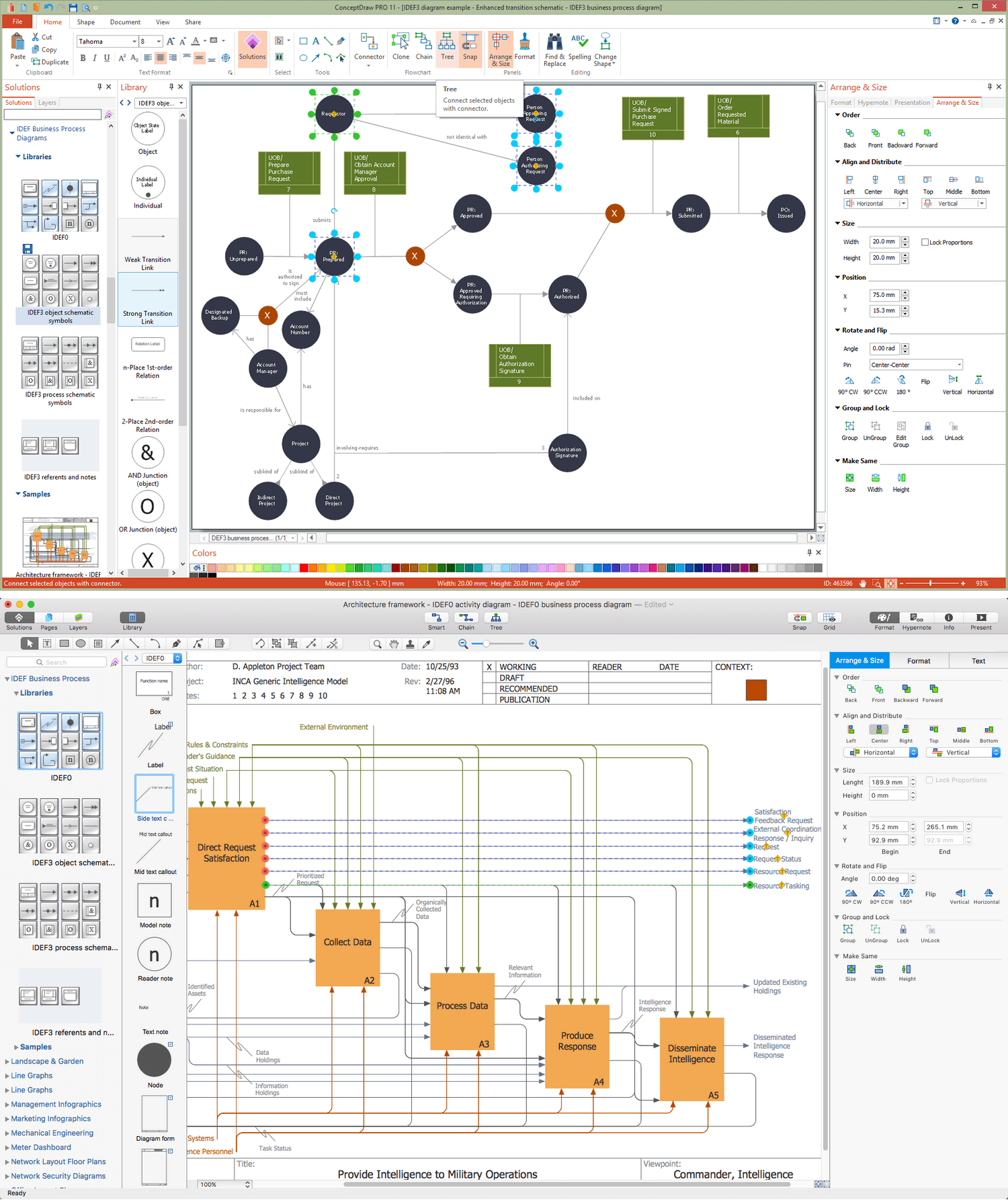
ConceptDraw DIAGRAM extended with IDEF Business Process Diagrams solution from the Business Processes area of ConceptDraw Solution Park is an ideal software for effective database design and drawing IDEF diagrams visually representing all steps of database design process.- ER Diagram For Banking Enterprise In Dbms
- Er Diagram For Banking System In Dbms
- Entity Relationship Diagram Examples | UML Class Diagram ...
- Er Diagram For Banking System With Explanation Pdf
- Dbms Er Diagram For Online Banking Pdf
- Entity-Relationship Diagram ( ERD ) | Erd For Banking Pdf
- Crows Foot Notation Of Banking System
- Draw An ER Diagram For Online Banking System
- Data Flow Diagrams (DFD) | Example Of Dfd And Erd Banking System
- Entity-Relationship Diagram ( ERD ) | Er Diagram Of Banking System ...
- Er Diagram For Banking Management System Including All Attribute
- Bank UML Diagram | UML Component for Bank | ER Diagram for ...
- Entity-Relationship Diagram ( ERD ) | Case Study Of Bank ...
- Simple Library Management System Database With Er Diagram In Pdf
- Simple Er Diagram For Bank Database
- Bank Management System Pdf File Dfd And Erd
- Bank UML Diagram | Communication Diagram UML2.0 ...
- Hotel Management System For Er Diagram Using Crows Foot Notation
- Er Diagram Of Material Management System


