Flowchart design. Flowchart symbols, shapes, stencils and icons


HelpDesk
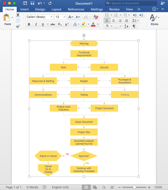
How to Add a Flowchart to MS Word Document
Technical Flow Chart

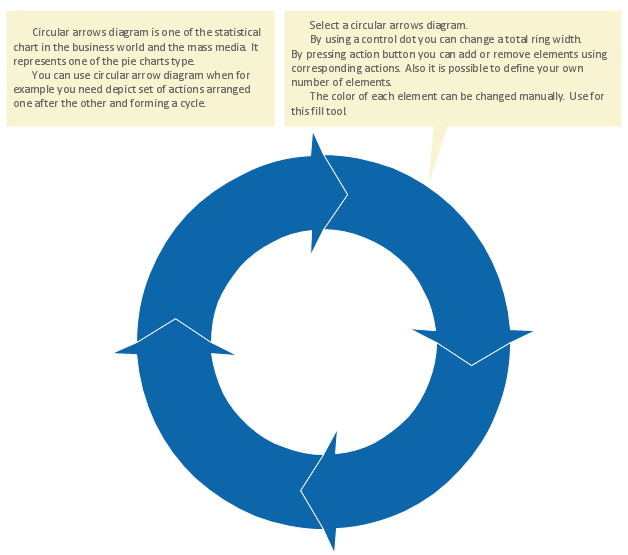
Circular Flow Diagram Template
Data Flow Diagram Symbols. DFD Library

UML Class Diagram Generalization Example UML Diagrams

Structured Systems Analysis and Design Method (SSADM) with ConceptDraw DIAGRAM

UML Diagram Visio

Program Evaluation and Review Technique (PERT) with ConceptDraw DIAGRAM

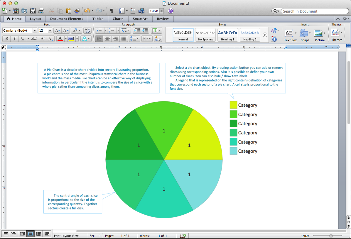
Pie Chart Word Template. Pie Chart Examples
- Diagram Of System Development Cycle
- Which Phase Of Sdlc Uses Dataflow Diagrams
- Draw A Flowchart Of Sdlc Phases
- In Which Phase Of Sdlc Flow Charts Are Drawn
- Data Flow Diagram Example In Sdlc Phases
- Describe Phases In The Sdlc With A Clear Flow Chart
- DFD - Process of account receivable | How to Create a Data Flow ...
- Data Flow Diagram Process | Circular Flow Diagram Template ...
- Draw A Flow Chart For Sdlc Process By Using Standard Symbols
- Cross-Functional Flowchart | Swmi Lane Diagram Sdlc