The vector stencils library "Logic gate diagram" contains 17 logical element symbols.
Use these shapes for drawing the logic gate diagrams in the ConceptDraw PRO diagramming and vector drawing software extended with the Electrical Engineering solution from the Engineering area of ConceptDraw Solution Park.
www.conceptdraw.com/ solution-park/ engineering-electrical
Use these shapes for drawing the logic gate diagrams in the ConceptDraw PRO diagramming and vector drawing software extended with the Electrical Engineering solution from the Engineering area of ConceptDraw Solution Park.
www.conceptdraw.com/ solution-park/ engineering-electrical
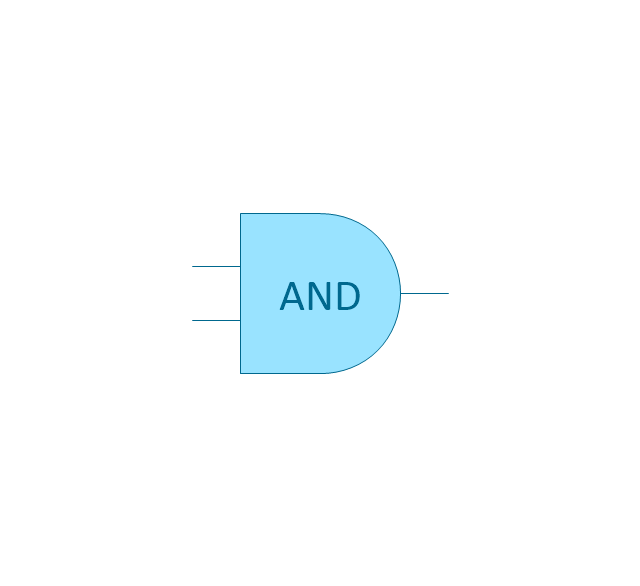
AND gate
OR gate

NOR gate (NOT OR)
-logic-gate-diagram---vector-stencils-library.png--diagram-flowchart-example.png)
NAND gate (NOT AND)
-logic-gate-diagram---vector-stencils-library.png--diagram-flowchart-example.png)
NOT gate (inverter)
-logic-gate-diagram---vector-stencils-library.png--diagram-flowchart-example.png)
EX-OR (Exclusive-OR) gate
-gate-logic-gate-diagram---vector-stencils-library.png--diagram-flowchart-example.png)
EX-NOR (Exclusive-NOR) gate
-gate-logic-gate-diagram---vector-stencils-library.png--diagram-flowchart-example.png)
Group

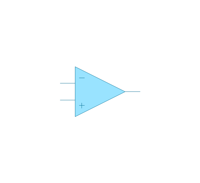
Operational Amplifier
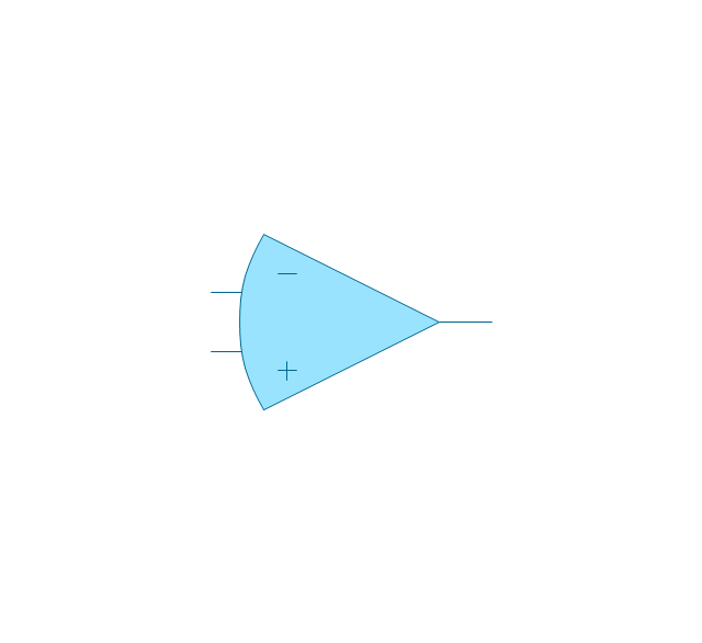
Alternative Operational Amplifier
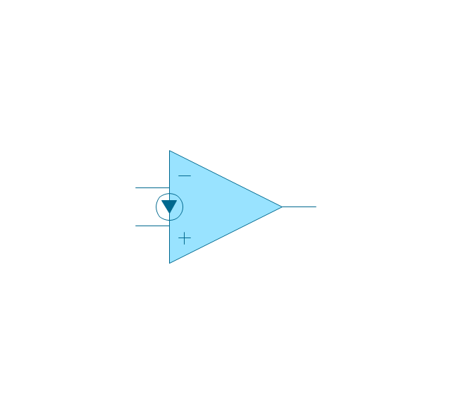
Norton op-amp
NOT gate (inverter)
-logic-gate-diagram---vector-stencils-library.png--diagram-flowchart-example.png)
NAND gate (NOT AND)
-logic-gate-diagram---vector-stencils-library.png--diagram-flowchart-example.png)
NOR gate (NOT OR)
-logic-gate-diagram---vector-stencils-library.png--diagram-flowchart-example.png)
Buffer

Gate with Open-Collector Output

Gate with Schmitt Trigger Input

Electrical Symbols — Logic Gate Diagram

The vector stencils library "Fault tree analysis diagrams" contains 12 symbols for drawing FTA diagrams in the ConceptDraw PRO diagramming and vector drawing software extended with the Fault Tree Analysis Diagrams solution from the Engineering area of ConceptDraw Solution Park.
www.conceptdraw.com/ solution-park/ engineering-fault-tree-analysis-diagrams
www.conceptdraw.com/ solution-park/ engineering-fault-tree-analysis-diagrams
AND gate

Priority AND gate

OR gate

Inhibit gate

XOR gate

Event

Basic event

Undeveloped event

House event

Conditional event

Transfer symbol

Voting gate

HelpDesk
How to Create a Fault Tree Analysis Diagram (FTD)

Electrical Drawing Software and Electrical Symbols

Electrical Symbols, Electrical Diagram Symbols

Wiring Diagrams with ConceptDraw DIAGRAM

The vector stencils library "Logic gate diagram" contains 17 element symbols for drawing the logic gate diagrams.
"To build a functionally complete logic system, relays, valves (vacuum tubes), or transistors can be used. The simplest family of logic gates using bipolar transistors is called resistor-transistor logic (RTL). Unlike simple diode logic gates (which do not have a gain element), RTL gates can be cascaded indefinitely to produce more complex logic functions. RTL gates were used in early integrated circuits. For higher speed and better density, the resistors used in RTL were replaced by diodes resulting in diode-transistor logic (DTL). Transistor-transistor logic (TTL) then supplanted DTL. As integrated circuits became more complex, bipolar transistors were replaced with smaller field-effect transistors (MOSFETs); see PMOS and NMOS. To reduce power consumption still further, most contemporary chip implementations of digital systems now use CMOS logic. CMOS uses complementary (both n-channel and p-channel) MOSFET devices to achieve a high speed with low power dissipation." [Logic gate. Wikipedia]
The symbols example "Design elements - Logic gate diagram" was drawn using the ConceptDraw PRO diagramming and vector drawing software extended with the Electrical Engineering solution from the Engineering area of ConceptDraw Solution Park.
Logic gate symbols

Electrical Symbols — Lamps, Acoustics, Readouts

Electrical Symbols — MOSFET

Electrical Symbols — Analog and Digital Logic

Electrical Symbols — Transistors

Electrical Symbols — IGFET

Electrical Symbols — Delay Elements

Electrical Symbols — Integrated Circuit

Mechanical Drawing Software

Electrical Symbols — Maintenance

Electrical Diagram

Mathematics Symbols

Electrical Symbols, Electrical Schematic Symbols

- Electrical Symbols — Logic Gate Diagram | How to Create a Fault ...
- Logic gate diagram - Vector stencils library | Symbol Ex Nor Gate
- Electrical Symbols — Logic Gate Diagram | 2-bit ALU - Logic gate ...
- Design elements - Logic gate diagram
- Design elements - Logic gate diagram | Draw The Logic Gate Symbol
- Gateways - Vector stencils library | Design elements - Gateways ...
- Amplifier - Circuit diagram | Electrical Symbols , Electrical Diagram ...
- Logic gate diagram - Template | Design elements - Logic gate ...
- Electrical Drawing Software and Electrical Symbols | Building ...
- Design elements - Fault tree analysis diagrams | How to Create a ...
- Gateways BPMN 1.2
- Xor Flow Digram
- Best Vector Drawing Application for Mac OS X | Fault tree analysis ...
- Graphical Symbols to use in EPC diagrams | An Event-driven ...
- Design elements - Logic gate diagram | Engineering | 2-bit ALU ...
- Logic gate diagram - Template | Electrical Symbols — Logic Gate ...
- Design elements - Logic gate diagram | Symbol Amplifier Diagram
- Electrical Symbols — Logic Gate Diagram | Electrical Drawing ...
- Electrical Symbols — Logic Gate Diagram | Electrical Symbols ...
- Electrical Engineering | Electrical Symbol For Safety Gate