Electrical Symbols — Inductors

Electrical Symbols, Electrical Diagram Symbols

Mechanical Drawing Symbols

Electrical Drawing Software and Electrical Symbols

Electrical Symbols — Transformers and Windings

Electrical Symbols — Resistors

Graphical Symbols to use in EPC diagrams

Wiring Diagrams with ConceptDraw DIAGRAM

Electrical Symbols — Lamps, Acoustics, Readouts

The vector stencils library "Inductors" contains 41 symbols of inductor elements for drawing electronic circuit diagrams.
"An inductor, also called a coil or reactor, is a passive two-terminal electrical component which resists changes in electric current passing through it. It consists of a conductor such as a wire, usually wound into a coil. When a current flows through it, energy is stored temporarily in a magnetic field in the coil. When the current flowing through an inductor changes, the time-varying magnetic field induces a voltage in the conductor, according to Faraday’s law of electromagnetic induction, which opposes the change in current that created it.
An inductor is characterized by its inductance, the ratio of the voltage to the rate of change of current, which has units of henries (H). Inductors have values that typically range from 1 µH (10-6H) to 1 H. Many inductors have a magnetic core made of iron or ferrite inside the coil, which serves to increase the magnetic field and thus the inductance. Along with capacitors and resistors, inductors are one of the three passive linear circuit elements that make up electric circuits. Inductors are widely used in alternating current (AC) electronic equipment, particularly in radio equipment. They are used to block the flow of AC current while allowing DC to pass; inductors designed for this purpose are called chokes. They are also used in electronic filters to separate signals of different frequencies, and in combination with capacitors to make tuned circuits, used to tune radio and TV receivers." [Inductor. Wikipedia]
The symbols example "Design elements - Inductors" was drawn using the ConceptDraw PRO diagramming and vector drawing software extended with the Electrical Engineering solution from the Engineering area of ConceptDraw Solution Park.
Inductor elements

AWS Simple Icons for Architecture Diagrams

The vector stencils library "Inductors" contains 41 symbols of inductor elements.
Use these shapes for drawing electronic circuit diagrams in the ConceptDraw PRO diagramming and vector drawing software extended with the Electrical Engineering solution from the Engineering area of ConceptDraw Solution Park.
www.conceptdraw.com/ solution-park/ engineering-electrical
Use these shapes for drawing electronic circuit diagrams in the ConceptDraw PRO diagramming and vector drawing software extended with the Electrical Engineering solution from the Engineering area of ConceptDraw Solution Park.
www.conceptdraw.com/ solution-park/ engineering-electrical
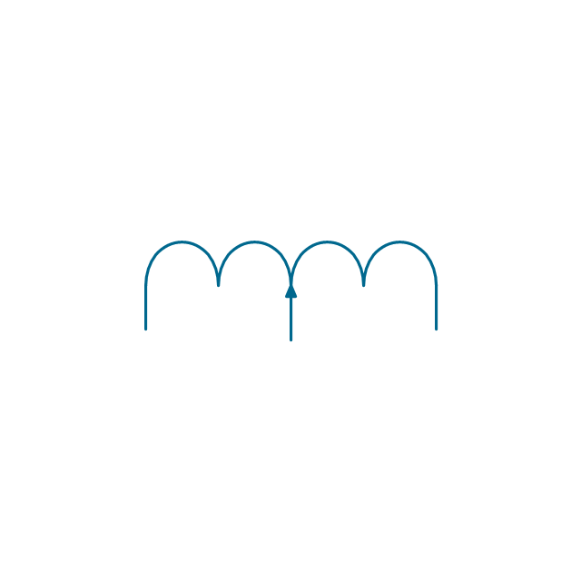
Air inductor, 3 taps

Air inductor, 2 taps

Air inductor, 1 tap

Air inductor

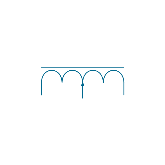
Air inductor, adjustable, 3 taps

Air inductor, adjustable, 2 taps

Air inductor, adjustable, 1 tap

Air inductor, adjustable
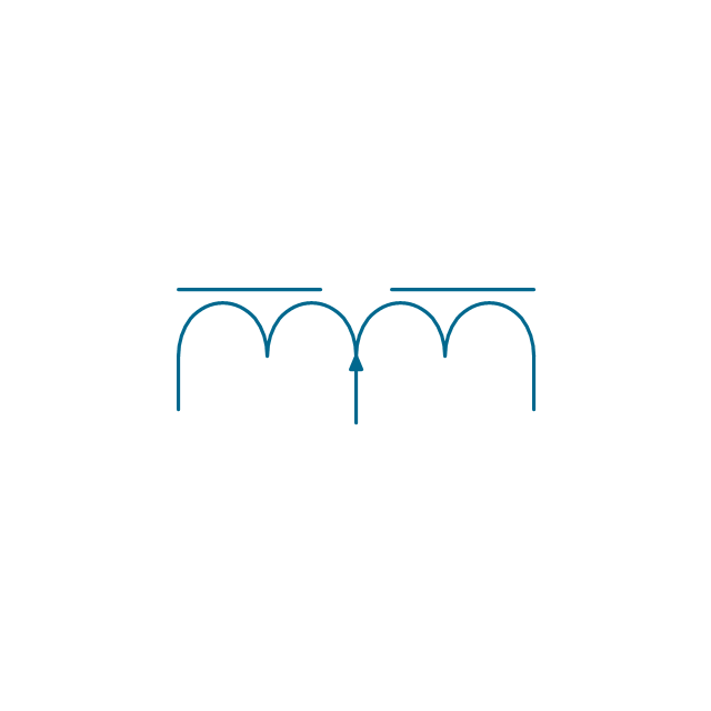
Air inductor, continuously adjustable, 3 taps

Air inductor, continuously adjustable, 2 taps

Air inductor, continuously adjustable, 1 tap

Air inductor, continuously adjustable

Magnetic inductor, 3 taps

Magnetic inductor, 2 taps

Magnetic inductor, 1 tap

Magnetic inductor

Magnetic inductor, adjustable, 3 taps

Magnetic inductor, adjustable, 2 taps

Magnetic inductor, adjustable, 1 tap

Magnetic inductor, adjustable
Magnetic inductor, continuously adjustable, 3 taps

Magnetic inductor, continuously adjustable, 2 taps

Magnetic inductor, continuously adjustable, 1 tap

Magnetic inductor, continuously adjustable

Magnetic inductor with gap, 3 taps

Magnetic inductor with gap, 2 taps

Magnetic inductor with gap, 1 tap

Magnetic inductor with gap

Magnetic inductor with gap, adjustable, 3 taps

Magnetic inductor with gap, adjustable, 2 taps

Magnetic inductor with gap, adjustable, 1 tap

Magnetic inductor with gap, adjustable
Magnetic inductor with gap, continuously adjustable, 3 taps

Magnetic inductor with gap, continuously adjustable, 2 taps

Magnetic inductor with gap, continuously adjustable, 1 tap

Magnetic inductor with gap, continuously adjustable

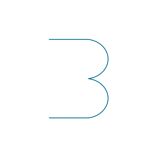
Half inductor
Permanent magnet

Magnet core
Ferrite core with reflector

Ferrite core

How To use House Electrical Plan Software


Electrical Symbols, Electrical Schematic Symbols

Electrical Symbols — Semiconductor Diodes

Electrical Symbols — Terminals and Connectors

Electrical Symbols — Power Sources

Electrical Symbols — Thermo

Electrical Diagram

Electrical Symbols — Composite Assemblies

- Electrical Symbols — Power Sources | Electrical Symbols ...
- Draw Symbol Of Iron Core Inductor
- Magnetic Core Symbol
- Design elements - Inductors | Draw Symbols Of The Following ...
- Electrical Symbols — Terminals and Connectors | Electrical Symbols ...
- Software To Draw Inductor And Capacitor
- Circuit Symbol For Laminated Core Inductor
- Symbol Of Choke Coil
- Design elements - Inductors | Electrical Symbols — Inductors ...
- Electrical Symbols — Inductors | Design elements - Inductors ...
- Electrical Symbols — Power Sources | Electrical Symbols ...
- Electrical Symbols , Electrical Diagram Symbols | Electrical Drawing ...
- Process Flow Diagram Symbols | Mechanical Drawing Symbols ...
- Mechanical Engineering | Mechanical Drawing Software ...
- Draw The Schematic Of Inductor
- Draw The Symbol Of Terminal And Conductor
- Draw The Symbols Of Choke
- Mechanical Drawing Symbols | Process Flow Diagram Symbols ...
- Engineering Drawing Alternating Current Symbol
- Mechanical Drawing Symbols