HelpDesk
How to Create an Electrical Diagram
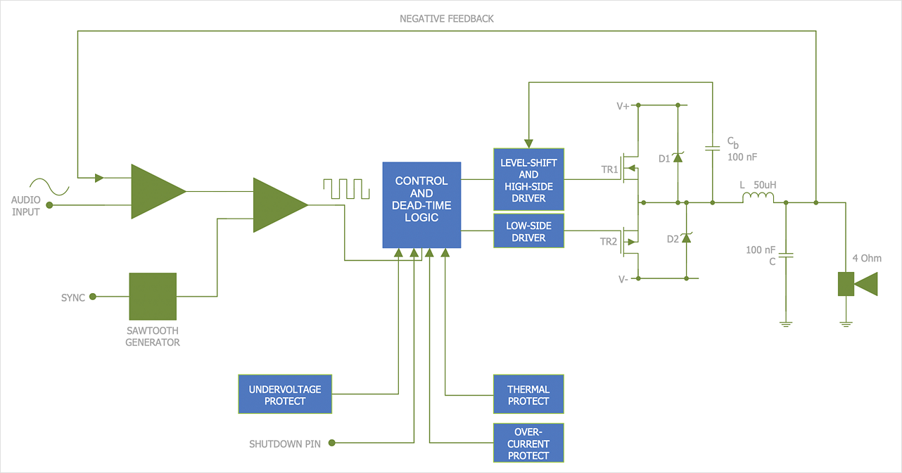
There are many different electric circuit symbols that can be used in a circuit diagram. Knowing how to read circuit diagrams is a useful skill not only for professionals but for any person who can start creating his own small home electronic projects. The circuit diagram shows the scheme of a location of components and connections of the electrical circuit using a set of standard symbols. It can be used for graphical documentation of electrical circuit components. The ability to create electrical diagrams and schematic using ConceptDraw DIAGRAM is delivered by the Electrical Engineering solution. The solution supplied with samples, templates, and libraries of design elements for drawing electrical schematics, digital and analog logic, circuit and wiring schematics and diagrams, power systems diagrams, maintenance and repair diagrams for electronics and electrical engineering.
 Engineering
This solution extends ConceptDraw DIAGRAM.4 with the ability to visualize industrial systems in electronics, electrical, chemical, process, and mechanical engineering.
Design Element: Rack Diagram for Network Diagrams
ConceptDraw DIAGRAM is perfect for software designers and software developers who need to draw Rack Diagrams.
Network Diagramming with ConceptDraw DIAGRAM
At the moment computer networks are widespread, various types of computer networks are constructed around the world, operate and interact with each other. There are many kinds of computer networks that differ in the transmission medium, in communications protocols, in size, topology, organizational intent, and also in territorial basis. There are popular such types of computer networks as Global Area Network (GAN), Wide Area Network (WAN), Metropolitan Area Network (MAN), Local Area Network (LAN). ConceptDraw DIAGRAM is a powerful network diagramming software, perfect for software engineers, software designers and software developers who need to draw Computer Network diagrams, designs, schematics, and network maps in no time. The pre-drawn shapes representing computers, network devices and smart connectors offered by ConceptDraw solutions help to create the accurate diagrams and documentation, represent computer network topologies and designs, depict Computer network architectures, logical, physical, cable networks, and vehicular networks.Basic Network Diagram
The Basic Network Diagram is an easy and effective way to design and document a simple network, it lets to represent visually and logically how the different network devices and computer equipment can be installed to meet the main business needs. ConceptDraw DIAGRAM software supplied with Computer Network Diagrams solution from the Computer and Networks area of ConceptDraw Solution Park is a perfect tool for drawing the Basic Computer Network diagrams, designs, schematics, and maps, network architectures, topologies, and layouts. Numerous vector libraries of network symbols, icons and components are incredibly helpful for IT and telecom engineers, stakeholders and end-users when designing Basic Network Diagrams, Common Network Diagrams, Common Network Topologies, 10Base-T Star Network Topologies, Bus Topology Diagrams, Communication Network Diagrams, System Designs, Regional Cable Head-End Diagrams, etc. Collection of predesigned samples and templates included to Computer Network Diagrams solution also greatly extends the capabilities of ConceptDraw DIAGRAM users.
- How To use House Electrical Plan Software | Electrical Drawing ...
- Wiring Diagrams with ConceptDraw PRO | Wiring Diagram Floor ...
- Wiring Diagrams with ConceptDraw PRO | How To use House ...
- Electrical Drawing Software | Wiring Diagrams with ConceptDraw ...
- Wiring Diagram Floor Software | Wiring Diagrams with ConceptDraw ...
- Electrical Schematic Symbols | Electrical Diagram Symbols | Wiring ...
- Wiring Diagrams with ConceptDraw PRO | Wiring Diagram Floor ...
- Wiring Diagrams with ConceptDraw PRO | Electrical Drawing ...
- How To use House Electrical Plan Software | Cafe electrical floor ...
- Wiring Diagrams with ConceptDraw PRO | Building Drawing ...
- Electrical Drawing Software | Electrical Diagram Software | Wiring ...
- Wiring Diagram Floor Software | Wiring Diagrams with ConceptDraw ...
- Wiring Diagrams with ConceptDraw PRO | Electrical Drawing ...
- How To use House Electrical Plan Software | Electrical Drawing ...
- Electrical Diagram Software | Wiring Diagram Floor Software ...
- Electrical Drawing Software | Wiring Diagrams with ConceptDraw ...
- Electrical Drawing Software | Circuits and Logic Diagram Software ...
- Wiring Diagrams with ConceptDraw PRO | How To use Electrical ...
- How to Create an Electrical Diagram Using ConceptDraw PRO ...
- Electrical Drawing Software | Electrical Diagram Symbols | Wiring ...

.png)

