 Plumbing and Piping Plans
Plumbing and Piping Plans solution extends ConceptDraw DIAGRAM.2.2 software with samples, templates and libraries of pipes, plumbing, and valves design elements for developing of water and plumbing systems, and for drawing Plumbing plan, Piping plan, PVC Pipe plan, PVC Pipe furniture plan, Plumbing layout plan, Plumbing floor plan, Half pipe plans, Pipe bender plans.
ConceptDraw Arrows10 Technology
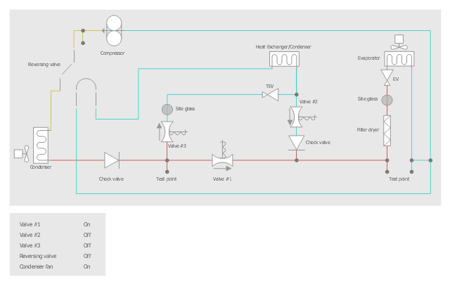
You can see that when you rotate a group, connectors change their angle, keeping their position inside of the grouped objects. If you decide to ungroup the objects, the connectors will adjust to keep lines parallel to the edges of the sheet. The magic of ConceptDraw Arrows10’s rotating group containing connectors, makes complex diagramming simple and easy. The way to connect objects has never been easier.This HVAC schematics sample depicts the house cool mode of central air pool heater. It was drawn on the base of the HVAC schematics in the post "Central Air Pool Heater" from the Nathan Stratton's blog.
"With House Cool Mode, hot gas leaves the compressor runs through the reversing value into the condenser where it condenses into a liquid. Valve #1 is ON so liquid is able to leave the outside unit and run through the filter dryer and site glass into the evaporator upstairs in the house where the liquid flashes into a gas as it passes through the expansion valve and absorbs heat from the air passing through the evaporator. The cold gas travels downstairs and outside to the compressor and the cycle starts all over again." [robotics.net/ projects/ central-air-pool-heater/ ]
The HVAC schematics example "Central air pool heater" was created using the ConceptDraw DIAGRAM diagramming and vector drawing software extended with the HVAC Plans solution from the Building Plans area of ConceptDraw Solution Park.
- Building Drawing Design Element: Piping Plan | Building Drawing ...
- How To Draw Plumbing Plans
- Plumbing and Piping Plans | Building Drawing Design Element ...
- Building Drawing Software for Designing Plumbing | Building ...
- Plumbing and Piping Plans | Building Drawing Software for ...
- Mechanical Drawing Software | Mechanical Drawing Symbols ...
- Building Drawing Design Element: Plumbing | Plumbing and Piping ...
- Plumbing and Piping Plans | Interior Design Piping Plan - Design ...
- How To use House Electrical Plan Software | Building Drawing ...
- How to Create a Residential Plumbing Plan | How To use House ...
- Plumbing and Piping Plans | How To use House Electrical Plan ...
- Waste Water Pipe Under Floor Details Drawing
- Home Electrical Plan | Plumbing and Piping Plans | How To use ...
- Restaurant water supply | Plumbing and Piping Plans | Building ...
- Building Drawing Software for Designing Plumbing | Plumbing and ...
- Plumbing and Piping Plans | Piping and Instrumentation Diagram ...
- 3 Bedroom Flat Plan Drawing
- Building Drawing Software for Design Sport Fields | Plumbing and ...
- Mechanical Drawing Symbols | Process Flow Diagram Symbols ...

