Process Flow Diagram
A Process Flow Diagram (PFD) is a diagram which shows the relationships between the main components in a system. Process Flow Diagrams are widely used by engineers in chemical and process engineering, they allows to indicate the general flow of plant process streams and equipment, helps to design the petroleum refineries, petrochemical and chemical plants, natural gas processing plants, and many other industrial facilities. ConceptDraw PRO diagramming and vector drawing software extended with powerful tools of Flowcharts Solution from the "What is a Diagram" Area of ConceptDraw Solution Park is effective for drawing: Process Flow Diagram, Flow Process Diagram, Business Process Flow Diagrams.Electrical Symbols — Stations
A power station is an industrial facility for the generation of electric power. Most power stations contain one or more generators, a rotating machine that converts mechanical power into electrical power. The relative motion between a magnetic field and a conductor creates an electrical current. The energy source harnessed to turn the generator varies widely. Most power stations in the world burn fossil fuels such as coal, oil, and natural gas to generate electricity. Others use nuclear power, but there is an increasing use of cleaner renewable sources such as solar, wind, wave and hydroelectric. 26 libraries of the Electrical Engineering Solution of ConceptDraw PRO make your electrical diagramming simple, efficient, and effective. You can simply and quickly drop the ready-to-use objects from libraries into your document to create the electrical diagram.Geo Map - Europe - Norway
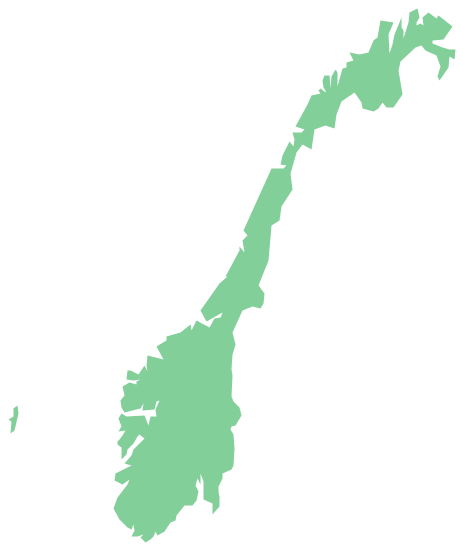
The vector stencils library Norway contains contours for ConceptDraw PRO diagramming and vector drawing software. This library is contained in the Continent Maps solution from Maps area of ConceptDraw Solution Park.- Mechanical Drawing Symbols | Circuit diagram - EL 34 schematics ...
- Drawing Illustration | Natural gas condensate - PFD | Affinity ...
- Amine treating unit schematic diagram | Natural gas condensate ...
- Natural gas condensate - PFD | Process Flow Chart | Types of ...
- Symbols In Gas Diagram
- Process Flow Diagram Symbols | Process Engineering | Technical ...
- Electrical Symbols, Electrical Diagram Symbols | Electrical Symbols ...
- Process Flow Chart | Process Flow Diagram | UML Class Diagram ...
- Schematic Diagram Of Gas Processing
- Mechanical Drawing Symbols | Process Flow Diagram | Valves ...
- Chemical Circuit Diagram
- Electrical Symbols — Stations | Electrical Symbols, Electrical ...
- Circuit diagram - EL 34 schematics | Electrical Drawing Software ...
- Process Flow Diagram Symbols | Chemical and Process ...
- Electrical Symbols, Electrical Diagram Symbols | Electrical Drawing ...
- Gas Plant Process Drawing
- Process Flowchart | Process Flow Diagram Symbols | Process Flow ...
- Chemistry | Water cycle diagram | Chemistry Symbols and Meanings ...
- Crude oil distillation unit - PFD | Jet fuel mercaptan oxidation treating ...
- Hydraulic circuits | Electrical Symbols, Electrical Diagram Symbols ...


