Entity Relationship Diagram - ERD - Software for Design Crows Foot ER Diagrams
_Win_Mac.png)

Entity Relationship Diagram Software

ConceptDraw DIAGRAM ER Diagram Tool

Entity Relationship Diagram Software Engineering

ER Diagram Tool

Entity-Relationship Diagram (ERD) with ConceptDraw DIAGRAM

Entity Relationship Diagram - ERD - Software for Design Chen ER Diagrams
_Win_Mac.png)
ER diagram tool for OS X
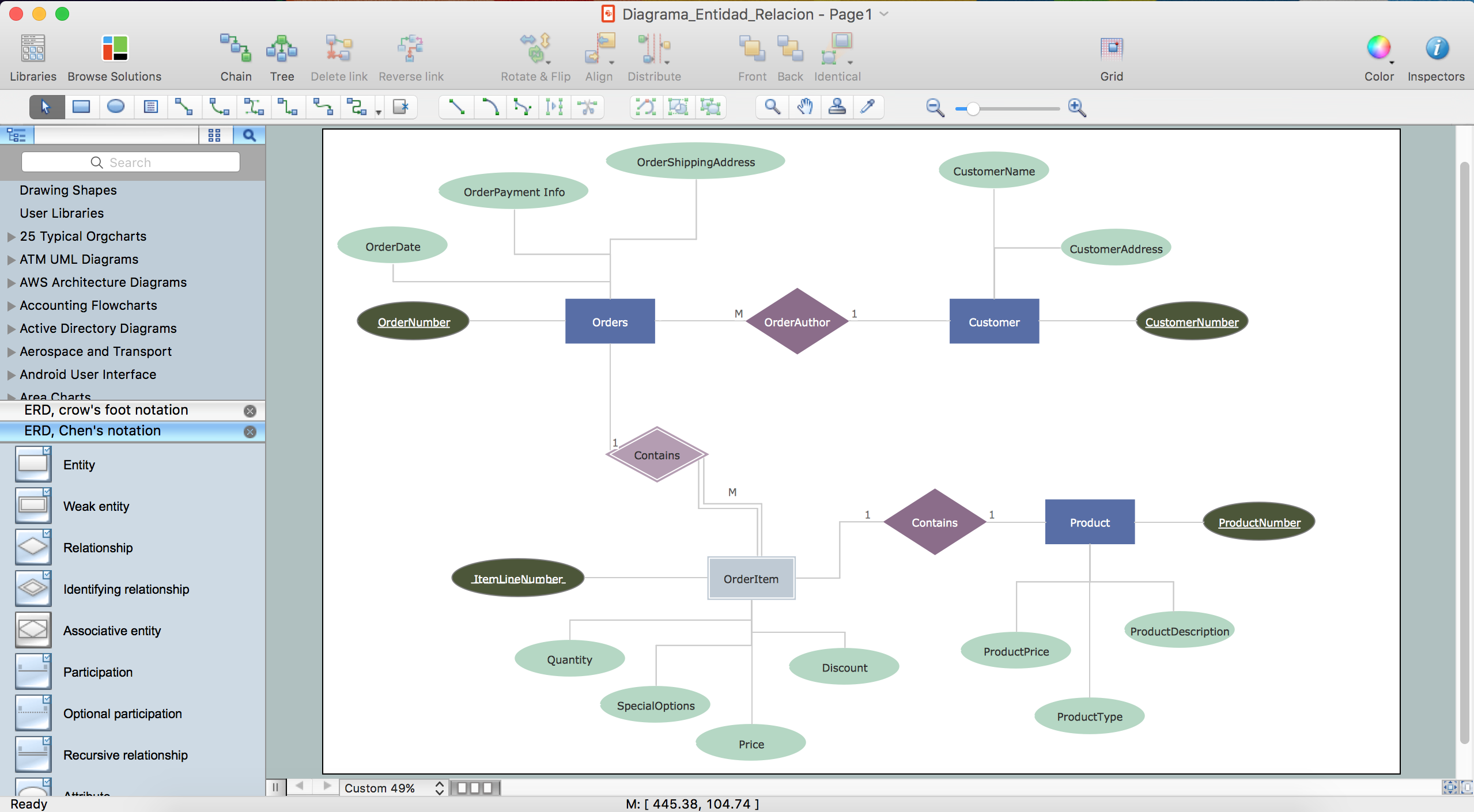
 Entity-Relationship Diagram (ERD)
An Entity-Relationship Diagram (ERD) is a visual presentation of entities and relationships. That type of diagrams is often used in the semi-structured or unstructured data in databases and information systems. At first glance ERD is similar to a flowch
ConceptDraw DIAGRAM ER Diagram Tool
- Entity Relationship Diagram - ERD - Software for Design Crows Foot ...
- Online Er Diagram Generator
- Entity Relationship Diagram Software Free Download
- ConceptDraw PRO Database Modeling Software | Diagram Drawing ...
- Chen Notation | Design elements - ER diagram (Chen notation ...
- Components of ER Diagram | Entity Relationship Diagram Symbols ...
- Entity Relationship Diagram Symbols | ConceptDraw PRO ER ...
- Id Card Generator Er Diagram
- Online Er Diagram Drawing Tool
- ConceptDraw PRO ER Diagram Tool | Entity Relationship Diagram ...