Electrical Symbols, Electrical Diagram Symbols
When drawing Electrical Schematics, Electrical Circuit Diagrams, Power Systems Diagrams, Circuit and Wiring Diagrams, Digital and Analog Logic Schemes, you will obligatory need the electrical symbols and pictograms to represent various electrical and electronic devices, such as resistors, wires, transistors, inductors, batteries, switches, lamps, readouts, amplifiers, repeaters, relays, transmission paths, semiconductors, generators, and many more. Today these symbols are internationally standardized, so the diagrams designed using them are recognizable and comprehensible by specialists from different countries. Electrical Engineering Solution included to ConceptDraw Solution Park provides 26 libraries with 926 commonly used electrical schematic and electrical engineering symbols making the reality the easy drawing of Electrical diagrams, schematics and blueprints. Now you need only a few minutes to create great-looking Electrical diagram, simply choose required electrical design elements from the libraries, drag them on the needed places at the document and connect in a suitable way.Electrical Symbols — IGFET
There are several types of insulated gate field-effect transistors (IGFETs) in common use. The early term metal oxide semiconductor field-effect transistor (MOSFET) is still in use, and MOSFET is usually acceptable as a generic term for IGFETs. The metal oxide, and the insulation in the IGFET, is the insulating material between the gate terminal and the substrate between the source and drain terminals. This insulator must have very low leakage, of course, but another requirement for good performance of the transistor is that the dielectric constant of the material must be very high. 26 libraries of the Electrical Engineering Solution of ConceptDraw DIAGRAM make your electrical diagramming simple, efficient, and effective. You can simply and quickly drop the ready-to-use objects from libraries into your document to create the electrical diagram.Restaurant Floor Plans Samples
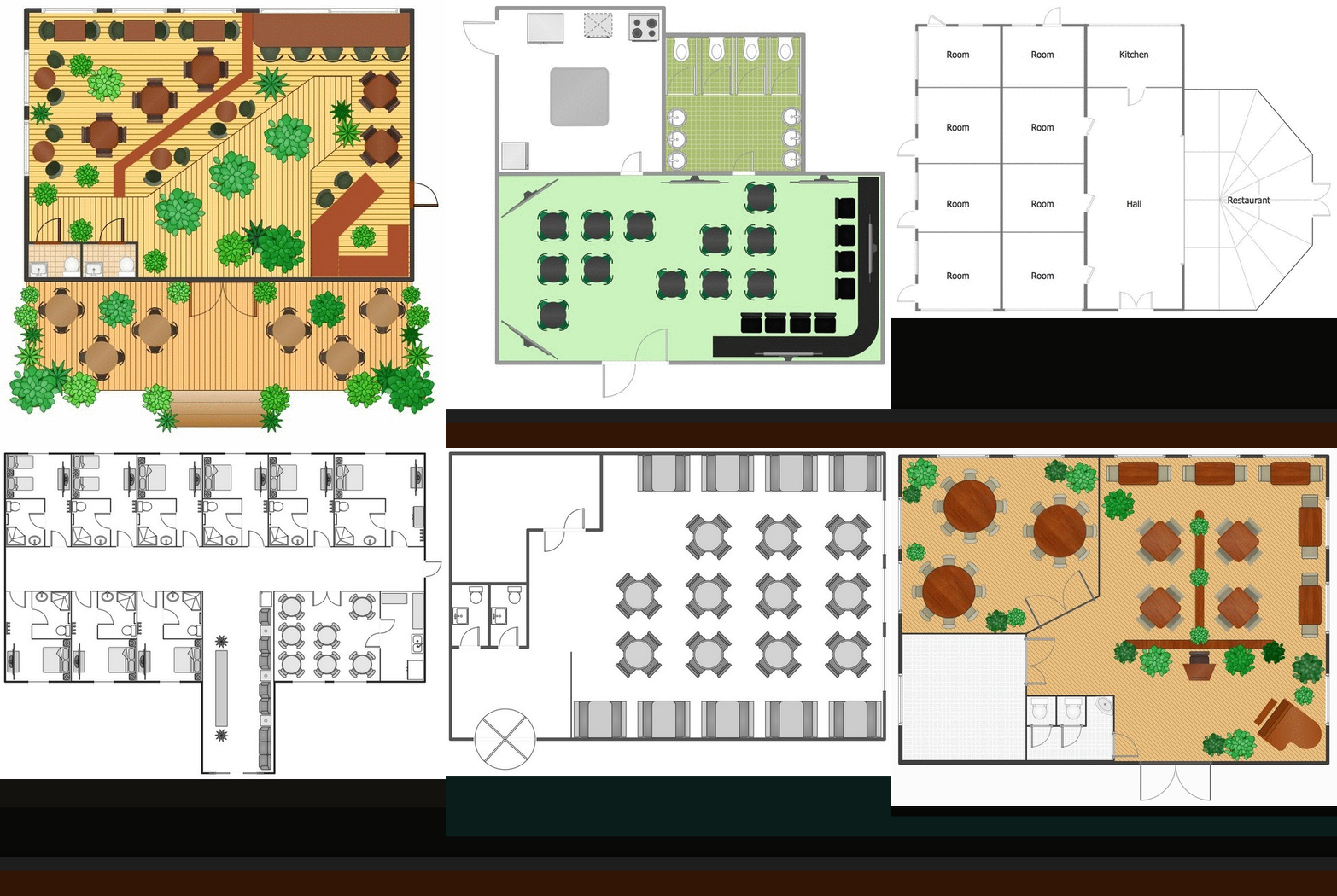
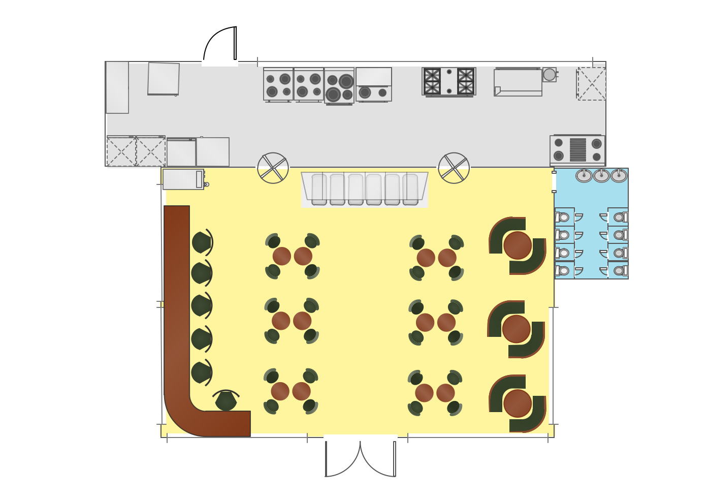
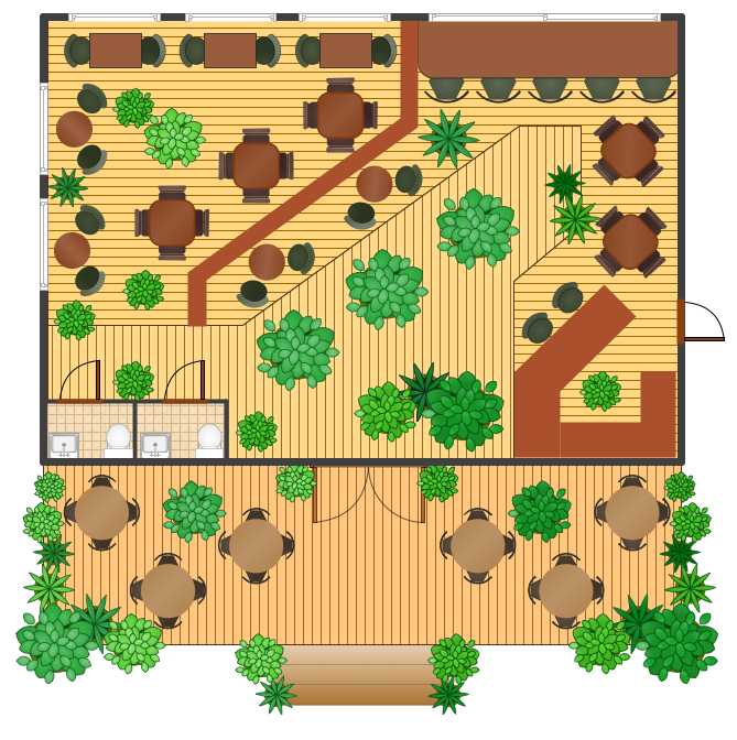
Imagine a place for socialization, comfort, relax and memories - restaurant. It is more than just food enterprise. Atmosphere and appearance of the whole restaurant and separately of each area, whether dining room, bar, waiting lounge, or restroom, are most important points. The idea behind the restaurant greatly determines materials, the flow of spaces and placement of walls. Design also should to be functional and practical to increase the staff productivity and sales. Thinking a lot about architecture, design and menu of the restaurant, don't forget about safety, ergonomy and profitability. When you planning to open a restaurant, you have create Restaurant Layout Plan, Restaurant Floor Plan, Restaurant Design Plan, Restaurant Electrical Plan, Emergency Plan, Plan of Furniture Arrangement, Landscape Design Plan. Sounds complicated? No worries, ConceptDraw DIAGRAM extended with Cafe and Restaurant Floor Plan solution contains variety of Restaurant Floor Plans samples, templates and predesigned objects which will help you in successful planning and designing your new restaurant or renovation an existing one.Piping and Instrumentation Diagram Software
Piping and Instrumentation Diagram is a technical sketch or drawing, which shows in details the piping system and instrumentation of a processing plant. Piping and Instrumentation Diagram is developed by process design engineers and technical engineers on the phase of plant design. This plan is necessary on the stages of plant construction and then is actively used by operators, instrumentation and piping engineers when operating the plant. ConceptDraw DIAGRAM software provides unique Plumbing and Piping Plans solution from Building Plans area of ConceptDraw Solution Park with 10 libraries of ready-to-use predesigned vector elements, templates and samples, to help you create professional Piping diagrams and schematics, Instrumentation diagrams, Plumbing plans and blueprints, Schemes of hot and cold water supply systems, Heating schemes, Mechanical diagrams, Diagrams of fluids, hydraulics, air and gas pipings, Technical drawings of waste water disposal systems, Schematics of industrial piping systems, Diagrams of ventilation systems, etc.Interior Design
Interior design is simultaneously the science and art directed on beautification of interior space with the aim to provide convenience, comfort, aesthetic for pleasant staying of people. Interior design is very multifaceted, it includes the processes of interior design development, space planning, research, communication with project's stakeholders, programming, management, coordination, site inspections, all they are realized directly by interior designers or under its supervision. Creation of interior design project lets you plan and optimize the space, improve the navigation inside large premises, develop the decoration project according to the chosen style, create the lighting plan, ventilation scheme, plumbing and heating plans, and schematic of furniture arrangement. Numerous solutions from Building Plans area of ConceptDraw Solution Park contain examples, samples, templates and vector stencils libraries helpful for development the interior designs of different styles, for professional creation the interior design drawings and using them for technical documentation.Store Layout Software
Creation of Store layout, Shop floor plan, Plans for warehouse and industrial premises, is one of the most important stages in development and design of the store, supermarket or shopping center. Layouts and plans help us clearly imagine our project after implementation, to consider all details, and improve it if necessary. The optimal store layout and design, proper zoning, well thought-out placement of the trade equipment, significantly increase the profit of the shop. ConceptDraw DIAGRAM is ideal store layout software that allows easy and professionally create varied Store layouts, Shop designs, Planograms, Designs for сommercial spaces, Cafe floor plans, Restaurant layouts, Office floor plans, House floor plans, and many others layouts thanks to the powerful tools offered by Floor Plans solution included to Building Plans area of ConceptDraw Solution Park. It includes many examples, quick-start templates and predesigned vector stencils libraries. With all this tools you don't need more to be professional artist to create great-looking Store layouts.Cafe Design
Cafes and restaurants are the places for relax and recreation, so the most important is their design and atmosphere of comfort, harmony, and uniqueness. So Cafe Design requires great creativity and efforts from the designers. ConceptDraw DIAGRAM software extended with Cafe and Restaurant Floor Plan solution from the Building Plans area of ConceptDraw Solution Park is the most simple way of displaying your Cafe Design ideas and plans first on the computer screen, and then on the paper.Types of Welding in Flowchart
This sample was created in ConceptDraw DIAGRAM diagramming and vector drawing software using the Flowcharts solution from the Diagrams area of ConceptDraw Solution Park. This sample shows the Flowchart that displays the solid-state welding processes, the types of welding.
 Event-driven Process Chain Diagrams
Event-Driven Process Chain Diagrams solution extends ConceptDraw DIAGRAM functionality with event driven process chain templates, samples of EPC engineering and modeling the business processes, and a vector shape library for drawing the EPC diagrams and EPC flowcharts of any complexity. It is one of EPC IT solutions that assist the marketing experts, business specialists, engineers, educators and researchers in resources planning and improving the business processes using the EPC flowchart or EPC diagram. Use the EPC solutions tools to construct the chain of events and functions, to illustrate the structure of a business process control flow, to describe people and tasks for execution the business processes, to identify the inefficient businesses processes and measures required to make them efficient.
- Plant Layout Plans | Diagram Of Electrical And Electronic Workshop ...
- Diagram Of A Workshop Layout
- How To use House Electrical Plan Software | Store Layout Software ...
- Diagram Of A Plumbing Workshop Layout
- Engineering Workshop Layout Block Diagram
- Plumbing and Piping Plans | Timeline Diagrams | Plant Layout Plans ...
- Electrical Engineering Workshop Layout
- Draw And Explain The Layout Electrical Power System
- Auto Repair Shop Floor Plan Download
- Computer Shop Floor Plan Design With Dimensions And Wiring


