The vector stencils library "Resistors" contains 14 element symbols of resistors for drawing electronic schematics, circuit diagrams and electrical drawings.
"A resistor is a passive two-terminal electrical component that implements electrical resistance as a circuit element. Resistors act to reduce current flow, and, at the same time, act to lower voltage levels within circuits. Resistors may have fixed resistances or variable resistances, such as those found in thermistors, varistors, trimmers, photoresistors and potentiometers.
The current through a resistor is in direct proportion to the voltage across the resistor's terminals. This relationship is represented by Ohm's law ...
Resistors are common elements of electrical networks and electronic circuits and are ubiquitous in electronic equipment. Practical resistors can be composed of various compounds and films, as well as resistance wires (wire made of a high-resistivity alloy, such as nickel-chrome). Resistors are also implemented within integrated circuits, particularly analog devices, and can also be integrated into hybrid and printed circuits." [Resistor. Wikipedia]
The shapes example "Design elements - Resistors" was drawn using the ConceptDraw PRO diagramming and vector drawing software extended with the Electrical Engineering solution from the Engineering area of ConceptDraw Solution Park.
Resistor symbols

Block Diagram Creator

Electrical Diagram

CAD Drawing Software for Making Mechanic Diagram and Electrical Diagram Architectural Designs


Electrical Symbols — Logic Gate Diagram

CAD Software for Architectural Designs
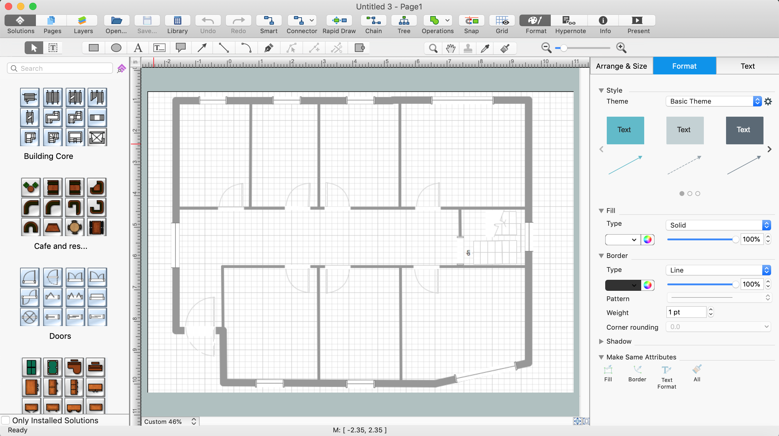
Use the libraries with a set of vector objects, templates and samples from the Floor Plans Solution from the Building Plans area of ConceptDraw Solution Park for designing your professional architectural designs.
Electrical Symbols — Resistors

Accounting Flowchart Symbols

Building Plan Software. Building Plan Examples

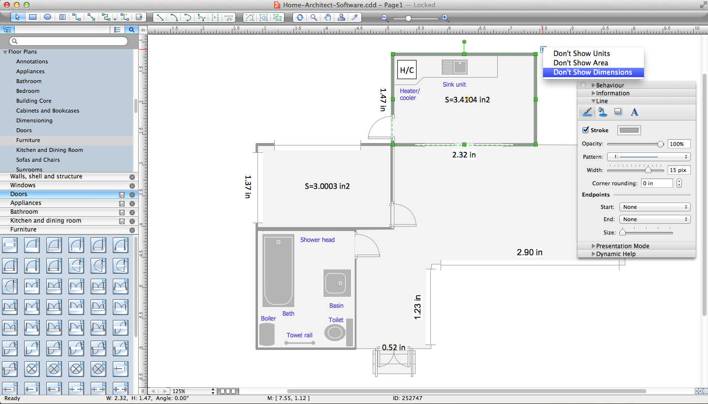
Home Architect Software. Home Plan Examples
Local area network (LAN). Computer and Network Examples
 diagram")

Network Glossary Definition

"A logic gate is an idealized or physical device implementing a Boolean function, that is, it performs a logical operation on one or more logical inputs, and produces a single logical output. Depending on the context, the term may refer to an ideal logic gate, one that has for instance zero rise time and unlimited fan-out, or it may refer to a non-ideal physical device...
Logic gates are primarily implemented using diodes or transistors acting as electronic switches, but can also be constructed using electromagnetic relays (relay logic), fluidic logic, pneumatic logic, optics, molecules, or even mechanical elements. With amplification, logic gates can be cascaded in the same way that Boolean functions can be composed, allowing the construction of a physical model of all of Boolean logic, and therefore, all of the algorithms and mathematics that can be described with Boolean logic.
Logic circuits include such devices as multiplexers, registers, arithmetic logic units (ALUs), and computer memory, all the way up through complete microprocessors, which may contain more than 100 million gates. In practice, the gates are made from field-effect transistors (FETs), particularly MOSFETs (metal–oxide–semiconductor field-effect transistors).
Compound logic gates AND-OR-Invert (AOI) and OR-AND-Invert (OAI) are often employed in circuit design because their construction using MOSFETs is simpler and more efficient than the sum of the individual gates.
In reversible logic, Toffoli gates are used." [Logic gate. Wikipedia]
The logic gate diagram template for the ConceptDraw PRO diagramming and vector drawing software is included in the Electrical Engineering solution from the Engineering area of ConceptDraw Solution Park.
Logic gate diagram

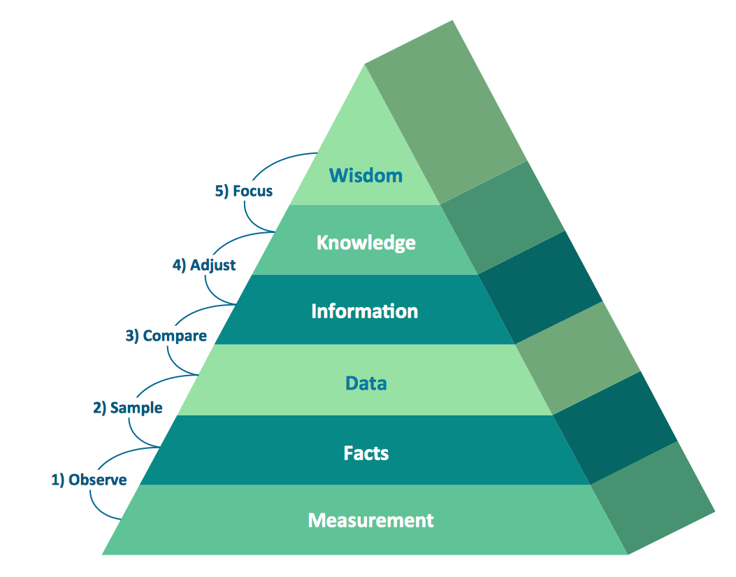
Pyramid Diagram
- How To use House Electrical Plan Software | Electrical Drawing ...
- Electrical Symbols, Electrical Diagram Symbols | Electrical Drawing ...
- Design elements - Electrical circuits
- Circuits and Logic Diagram Software | Draw The Symbol And Also ...
- Electrical Drawing Software and Electrical Symbols | Circuits and ...
- How to Create an Electrical Diagram Using ConceptDraw PRO ...
- Design elements - Resistors | Design elements - Electrical circuits ...
- CAD Drawing Software for Making Mechanic Diagram and Electrical ...
- Circuits and Logic Diagram Software | Electric and Telecom Plans ...
- Design elements - Electrical circuits | Design elements - Electrical ...
- Logic gate diagram - Template | Circuits and Logic Diagram ...
- Electrical Drawing Software and Electrical Symbols | Electrical ...
- Electronic Circuit Diagram Assemblies Free Video Download
- Circuits and Logic Diagram Software | Building Drawing Design ...
- Amplifier Circuit Schematics
- Circuits and Logic Diagram Software | Samples of Flowchart ...
- Electrical Symbols, Electrical Diagram Symbols | Electrical Drawing ...
- Electronic Schematic
- Electrical Engineering | Electrical Engineering | Electrical Diagram ...
- Design elements - Logic gate diagram | Electrical Symbols — Logic ...