Process Flow Diagram Symbols

Entity Relationship Diagram Software Engineering

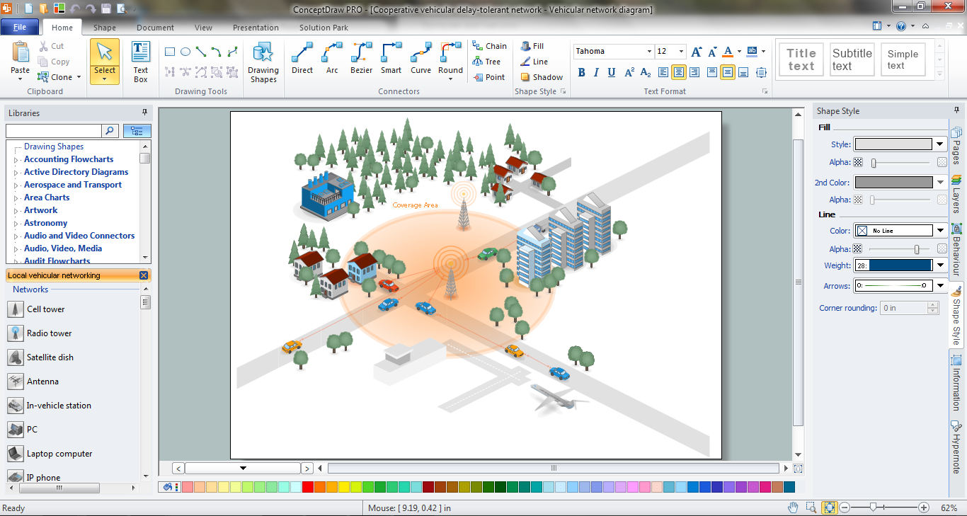
 Chemical and Process Engineering
This chemical engineering solution extends ConceptDraw DIAGRAM.9.5 (or later) with process flow diagram symbols, samples, process diagrams templates and libraries of design elements for creating process and instrumentation diagrams, block flow diagrams (BFD
Electrical Symbols, Electrical Diagram Symbols

 Mechanical Engineering
This solution extends ConceptDraw DIAGRAM.9 mechanical drawing software (or later) with samples of mechanical drawing symbols, templates and libraries of design elements, for help when drafting mechanical engineering drawings, or parts, assembly, pneumatic,
Network Engineering
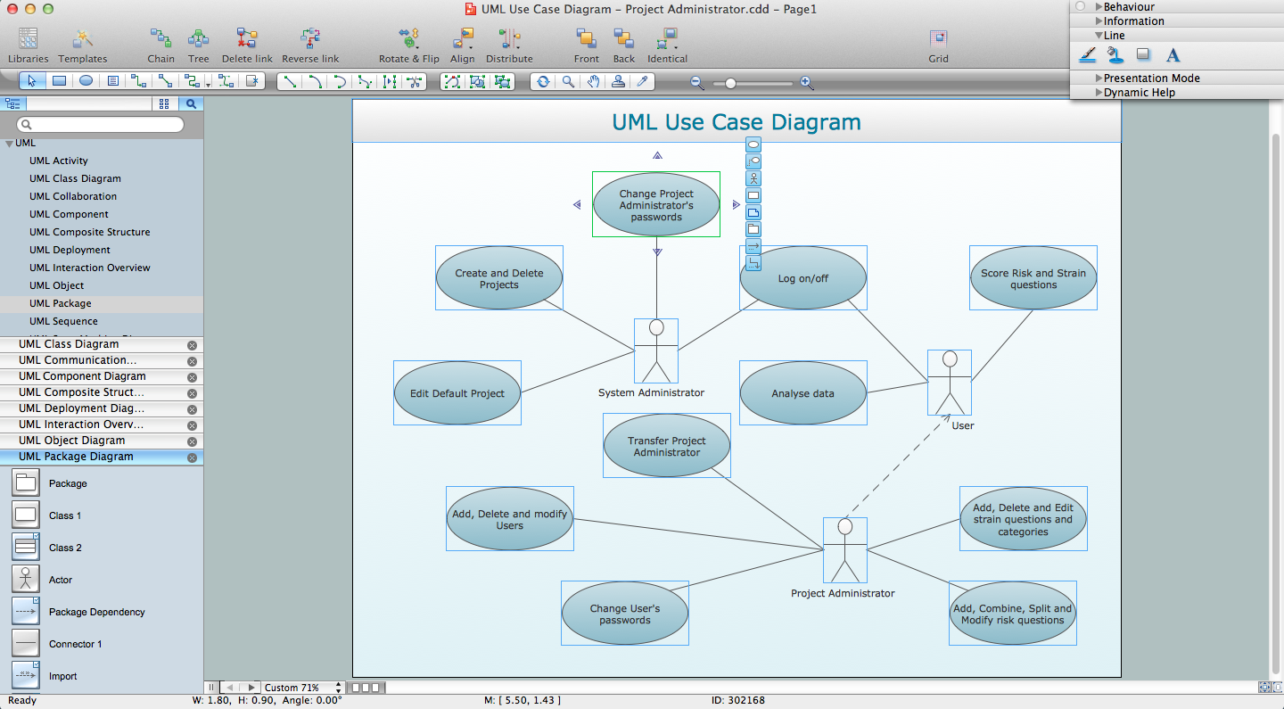
UML for Software Engineers
Electrical Engineering

- Systems engineering improvement | Venn Diagrams | Chemical and ...
- Bank System | Bank UML Diagram | Software Engineer Package ...
- Workflow Diagrams | Software Engineer Package | Professional ...
- Process Flowchart | Process Engineering | Process Flow Diagram ...
- Fishbone Diagram Example | How Do Fishbone Diagrams Solve ...
- Engineer Home Diagram
- Chemical Engineering Drawing Diagram Software
- Process Flow Diagram Symbols | Design elements - Heating ...
- Process Flowchart | Process Flow Diagram Symbols | Engineering ...
- Electrical Engineering | Electrical Symbols, Electrical Diagram ...