HelpDesk
How to Draw a Process Flow Diagram in ConceptDraw PRO
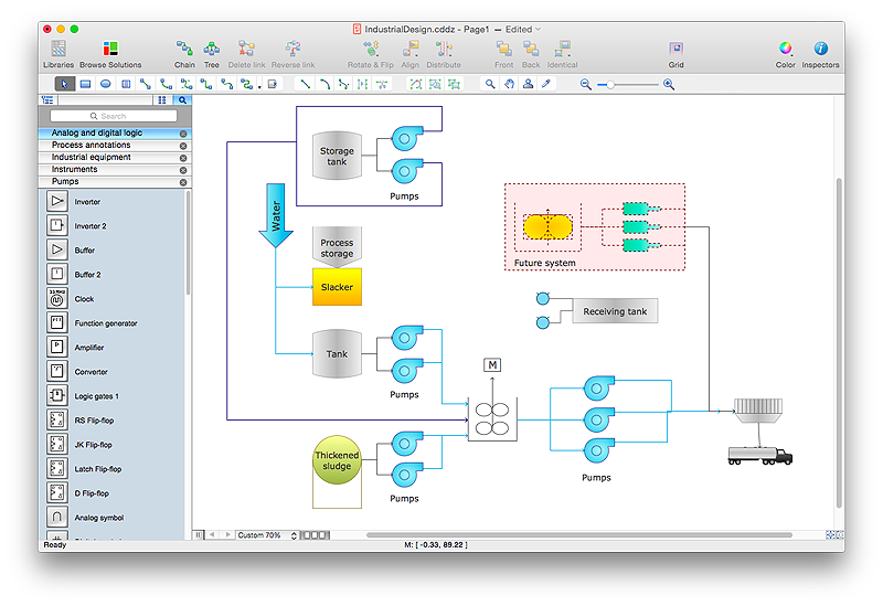
Process Flow diagrams are used in chemical and process engineering to show the flow of chemicals and the equipment involved in the process. When it comes to creating a process flow diagram, it's important to use software that is capable of describing a wide range of processes, using techniques and graphical notation that are easily recognized by engineering workers. An ideal drawing platform will utilize functions that can cope with the output of a high volume of engineering processes, that may change rapidly from development to implementation stages. ConceptDraw PRO, with the extended functionality of the Chemical and Process Engineering Diagrams solution, is the ideal medium for creating designs of this type. The Chemical and Process Engineering Diagrams solution complements this feature with a library of selected icons to represent various steps — all instantly recognizable and applicable to a wide user base. ConceptDraw PRO allows you to draw the Process Flow diagram easily using the set of special libraries.
 Chemical and Process Engineering
This chemical engineering solution extends ConceptDraw PRO v.9.5 (or later) with process flow diagram symbols, samples, process diagrams templates and libraries of design elements for creating process and instrumentation diagrams, block flow diagrams (BFD
- Industrial Engineering Layout Software
- How To use House Electrical Plan Software | Electrical Drawing ...
- What Is The Instrument Use For Drawing Floor Plan
- Factory layout floor plan | Piping and Instrumentation Diagram ...
- Piping and Instrumentation Diagram Software | Mechanical Drawing ...
- Electrical Drawing Software and Electrical Symbols | Process ...
- Piping and Instrumentation Diagram Software | Home Electrical Plan ...
- How To Draw A Floor Plan With A Drawing Instrument
- Piping and Instrumentation Diagram Software | Building Drawing ...
- Piping and Instrumentation Diagram Software | Process Flowchart ...
- Software For Drawing Electrical Instruments
- Piping and Instrumentation Diagram Software | Mechanical Drawing ...
- Piping and Instrumentation Diagram Software | Interior Design ...
- Piping and Instrumentation Diagram Software | Design elements ...
- Piping and Instrumentation Diagram Software | Building Drawing ...
- Building Drawing Design Element: Piping Plan | Plumbing and ...
- Plumbing and Piping Plans | Building Drawing Design Element ...
- Process Flowchart | Piping and Instrumentation Diagram Software ...
- Piping and Instrumentation Diagram Software | Interior Design ...
- CAD Drawing Software for Making Mechanic Diagram and Electrical
