 Entity-Relationship Diagram (ERD)
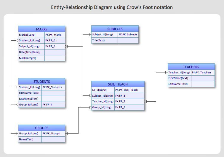
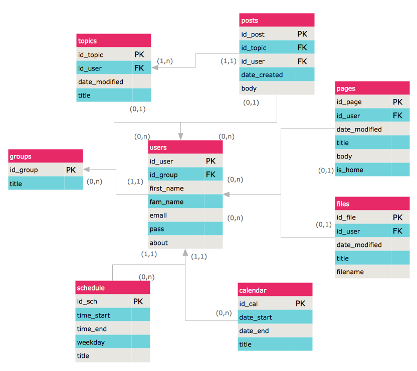
An Entity-Relationship Diagram (ERD) is a visual presentation of entities and relationships. That type of diagrams is often used in the semi-structured or unstructured data in databases and information systems. At first glance ERD is similar to a flowch
 Wireless Networks
The Wireless Networks Solution extends ConceptDraw PRO software with professional diagramming tools, set of wireless network diagram templates and samples, comprehensive library of wireless communications and WLAN objects to help network engineers and designers efficiently design and create Wireless network diagrams that illustrate wireless networks of any speed and complexity, and help to identify all required equipment for construction and updating wireless networks, and calculating their costs.
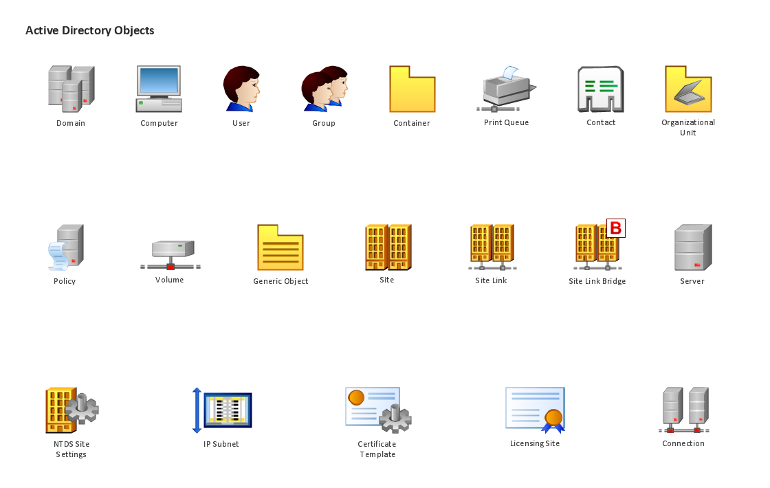
Design Element: Active Directory for Network Diagrams
ConceptDraw PRO is perfect for software designers and software developers who need to draw Active Directory Network Diagrams.
Design Element: Rack Diagram for Network Diagrams
ConceptDraw PRO is perfect for software designers and software developers who need to draw Rack Diagrams.
 ConceptDraw Solution Park
ConceptDraw Solution Park collects graphic extensions, examples and learning materials
 Vehicular Networking
Network engineering is an extensive area with wide range of applications. Depending to the field of application, network engineers design and realize small networks or complex networks, which cover wide territories. In latter case will be ideal recourse to specialized drawing software, such as ConceptDraw PRO.
 Computer Network Diagrams
Computer Network Diagrams solution extends ConceptDraw PRO software with samples, templates and libraries of vector icons and objects of computer network devices and network components to help you create professional-looking Computer Network Diagrams, to plan simple home networks and complex computer network configurations for large buildings, to represent their schemes in a comprehensible graphical view, to document computer networks configurations, to depict the interactions between network's components, the used protocols and topologies, to represent physical and logical network structures, to compare visually different topologies and to depict their combinations, to represent in details the network structure with help of schemes, to study and analyze the network configurations, to communicate effectively to engineers, stakeholders and end-users, to track network working and troubleshoot, if necessary.
HelpDesk
How to Create an Entity-Relationship Diagram Using ConceptDraw Solution Park
An entity-relationship diagram (ERD)is used in a database modeling process. ERD diagram shows a graphical representation of objects or concepts within an information system and their relationships.The ability to describe a database using the Entity-Relationship model is delivered by the ConceptDraw ERD solution.
 Entity-Relationship Diagram (ERD)
Entity-Relationship Diagram (ERD) solution extends ConceptDraw PRO software with templates, samples and libraries of vector stencils from drawing the ER-diagrams by Chen's and crow’s foot notations.
HelpDesk
How to Create an ERD Diagram
ERD (entity relationship diagram) is used to show the logical structure of databases. It represents the interrelationships between components of database (entities). Entity relationship diagrams are a widely used in software engineering. Using ERD software engineers can control the every aspect of database development. ER diagram can be used as guide for testing and communicating before the release of software product. ERD displays data as entities that are connected with connections that show the relationships between entities. There is some ERD notations used by data bases developers for representing the relationships between the data objects. ConceptDraw PRO and its ERD solution allow you to build ERD diagram of any notation.- Entity Relationship Diagram Examples | Examples of Flowcharts ...
- Fully Connected Network Topology Diagram | ConceptDraw PRO ...
- Entity -Relationship Diagram (ERD) | Social Media Response | How ...
- Entity Relationship Diagram Symbols | Data Flow Diagram Symbols ...
- Activity on Node Network Diagramming Tool | PERT chart ...
- Entity -Relationship Diagram (ERD) | Aerospace and Transport ...
- Entity Relationship Diagram Software Engineering | Professional ...
- | Cisco Network Icons | Network Diagram Software Home Area ...
- Business Productivity Diagramming | Entity Relationship Diagram ...
- Entity -Relationship Diagram (ERD) | Telecommunication Network ...
- Mesh Network Topology Diagram | Mesh Network . Computer and ...
- How to Build a Flowchart | Entity -Relationship Diagram (ERD) with ...
- Basic Flowchart Symbols and Meaning | Entity Relationship ...
- Metropolitan area networks (MAN). Computer and Network Examples
- Basic Flowchart Symbols and Meaning | UML Use Case Diagram ...
- Entity -Relationship Diagram (ERD) | Enterprise Architecture ...
- Entity -Relationship Diagram (ERD) | Metro Map | Interactive Voice ...
- Entity -Relationship Diagram (ERD) | How to Create an Entity ...
- Entity -Relationship Diagram (ERD) | ER Diagram Tool | Entity ...

.png)

