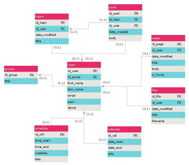
 Entity-Relationship Diagram (ERD)
Entity-Relationship Diagram (ERD) solution extends ConceptDraw PRO software with templates, samples and libraries of vector stencils from drawing the ER-diagrams by Chen's and crow’s foot notations.
This ERD sample was redesigned from the Wikimedia Commons file: Entity-Relationship Model (diagram).png. [commons.wikimedia.org/ wiki/ File:Entity-Relationship_ Model_ %28diagram%29.png]
"An entity-relationship model is a systematic way of describing and defining a business process. The process is modeled as components (entities) that are linked with each other by relationships that express the dependencies and requirements between them...
Entities may have various properties (attributes) that characterize them. Diagrams created to represent these entities, attributes, and relationships graphically are called entity–relationship diagrams.
An ER model is typically implemented as a database. In the case of a relational database, which stores data in tables, which represent the entities. Some data fields in these tables point to indexes in other tables; such pointers represent the relationships." [Entity–relationship model. Wikipedia]
The ERD example "Entity-relationship model diagram" was created using the ConceptDraw PRO diagramming and vector drawing software extended with the Entity-Relationship Diagram (ERD) solution from the Software Development area of ConceptDraw Solution Park.
- Entity Relationship Diagram Software for Design Crows Foot ER ...
- Components of ER Diagram | Entity Relationship Diagram Symbols ...
- Data Modeling with Entity Relationship Diagram
- Design elements - ER diagram (Chen notation) | Entity - Relationship ...
- | Entity Relationship Diagram Symbols and Meaning ERD Symbols ...
- Entity Relationship Diagram Examples | Data Modeling with Entity ...
- Entity Relationship Model Ssadm
- Data Modeling with Entity Relationship Diagram
- Data Modeling with Entity Relationship Diagram | Entity Relationship ...
- The Entity Relationship Model
- Entity Relationship Model In Software Engineering
- Entity Relationship Diagram Examples
- Entity Relationship Diagram Software Engineering | Entity ...
- Symbols Used In Entity Relation Models
- Entity Relationship Model Example
- Entity Relationship Diagram Software for Mac | Entity - Relationship ...
- Entity - Relationship Diagram (ERD)
- Entity Relationship Diagram Chen Model
- Entity Relationship Diagram Software Engineering | Entity ...
