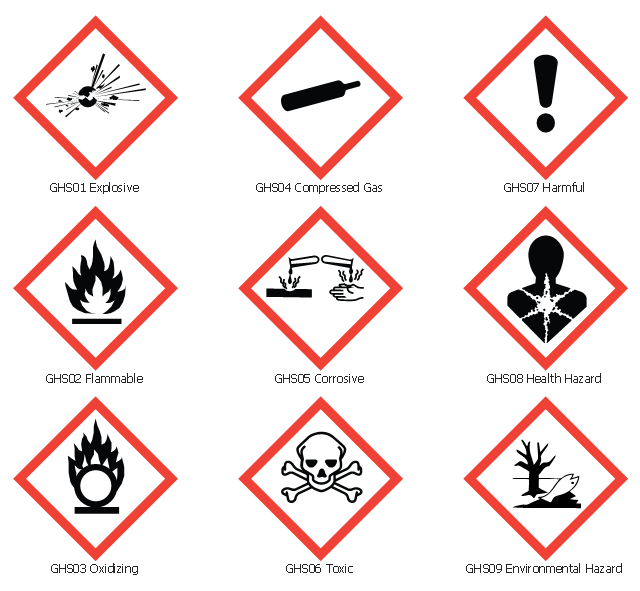
The vector stencils library "GHS hazard pictograms" contains 9 chemical hazard symbols.
Use it in ConceptDraw PRO software to design your chemical safety infographics, labels of containers with hazardous materials, International Chemical Safety Cards (ICSC), manufacturers' Safety Data Sheets (SDS), and Material Safety Data Sheets (MSDS).
"Hazard pictograms form part of the international Globally Harmonized System of Classification and Labelling of Chemicals (GHS). Two sets of pictograms are included within the GHS: one for the labelling of containers and for workplace hazard warnings, and a second for use during the transport of dangerous goods. ...
Hazard pictograms are one of the key elements for the labelling of containers under the GHS, along with:
- an identification of the product;
- a signal word – either Danger or Warning – where necessary;
- hazard statements, indicating the nature and degree of the risks posed by the product;
- precautionary statements, indicating how the product should be handled to minimize risks to the user (as well as to other people and the general environment);
- the identity of the supplier (who might be a manufacturer or importer)." [GHS hazard pictograms. Wikipedia]
The chemical hazard symbols example "Design elements - GHS hazard pictograms" is included in the GHS Hazard Pictograms solution from the Engineering area of ConceptDraw Solution Park.
Chemical safety symbols
The vector stencils library "HVAC equipment" contains 26 symbols of HVAC equipment as pumps, fans, condensers, pipe coils, silencers, etc.
Use the design elements library "HVAC equipment" for drawing the HVAC system diagrams, heating, ventilation, air conditioning, refrigeration, automated building control and environmental control system layout floor plans using the ConceptDraw PRO diagramming and vector drawing software.
"HVAC (heating, ventilation, and air conditioning) is the technology of indoor and vehicular environmental comfort. HVAC system design is a subdiscipline of mechanical engineering, based on the principles of thermodynamics, fluid mechanics, and heat transfer. Refrigeration is sometimes added to the field's abbreviation as HVAC&R or HVACR, or ventilating is dropped as in HACR (such as the designation of HACR-rated circuit breakers).
HVAC is important in the design of medium to large industrial and office buildings such as skyscrapers and in marine environments such as aquariums, where safe and healthy building conditions are regulated with respect to temperature and humidity, using fresh air from outdoors." [HVAC. Wikipedia]
The shapes library "HVAC equipment" is contained in the HVAC Plans solution from the Building Plans area of ConceptDraw Solution Park.
HVAC equipment symbols

"HVAC (stands for Heating, Ventilation and Air Conditioning) is a control system that applies regulation to a heating and/ or air conditioning system. Usually a sensing device is used to compare the actual state (e.g., temperature) with a target state. Then the control system draws a conclusion what action has to be taken (e.g., start the blower).
More complex HVAC systems can interface to Building Automation System (BAS) to allow the building owners to have more control over the heating or cooling units. The building owner can monitor the system and respond to alarms generated by the system from local or remote locations." [HVAC control system. Wikipedia]
The vector stencils library "HVAC control equipment" contains 48 symbols of heating, ventilation, air conditioning, refrigeration and automated building control equipment.
Use the design elements library HVAC control equipment to draw HVAC plans, schematic diagrams of heating, ventilation, air conditioning, refrigeration and automated building control systems, environmental control design building plans and equipment layouts using the ConceptDraw PRO diagramming and vector drawing software.
The shapes library HVAC control equipment is contained in the HVAC Plans solution from the Building Plans area of ConceptDraw Solution Park.
HVAC control equipment symbols

The vector stencils library "HVAC controls" contains 23 symbols of HVAC controls (sensors, actuators, timers, controllers, I/ O points).
"HVAC (... Heating, Ventilation and Air Conditioning) is a control system that applies regulation to a heating and/ or air conditioning system. ...
Central controllers and most terminal unit controllers are programmable, meaning the direct digital control program code may be customized for the intended use. The program features include time schedules, setpoints, controllers, logic, timers, trend logs, and alarms. The unit controllers typically have analog and digital inputs that allow measurement of the variable (temperature, humidity, or pressure) and analog and digital outputs for control of the transport medium (hot/ cold water and/ or steam). Digital inputs are typically (dry) contacts from a control device, and analog inputs are typically a voltage or current measurement from a variable (temperature, humidity, velocity, or pressure) sensing device. Digital outputs are typically relay contacts used to start and stop equipment, and analog outputs are typically voltage or current signals to control the movement of the medium (air/ water/ steam) control devices such as valves, dampers, and motors." [HVAC control system. Wikipedia]
Use the design elements library "HVAC controls" for drawing the HVAC system diagrams, controls drawings, and automated building control and environmental control system layuout floor plans using the ConceptDraw PRO diagramming and vector drawing software.
The shapes library "HVAC controls" is included in the HVAC Plans solution from the Building Plans area of ConceptDraw Solution Park.
HVAC control symbols

The vector stencils library Initiation and annunciation contains 9 symbols of Fire Alarm Control Panel (FACP) or Fire Alarm Control Unit (FACU) elements, triggering devices, audible alarm systems, timers, security control equipment, and recording devices.
"A Fire Alarm Control Panel (FACP), or Fire Alarm Control Unit (FACU), is the controlling component of a Fire Alarm System. The panel receives information from environmental sensors designed to detect changes associated with fire, monitors their operational integrity and provides for automatic control of equipment, and transmission of information necessary to prepare the facility for fire based on a predetermined sequence. The panel may also supply electrical energy to operate any associated sensor, control, transmitter, or relay. There are four basic types of panels: coded panels, conventional panels, addressable panels, and multiplex systems." [Fire alarm control panel. Wikipedia]
Use the shapes library Initiation and annunciation to draw layout floor plans, communications schematics and wiring diagrams of security systems using the ConceptDraw PRO diagramming and vector drawing software.
The design elements library Initiation and annunciation is included in the Security and Access Plans solution from the Building Plans area of ConceptDraw Solution Park.
Initiation and annunciation symbols

The vector stencils library "HVAC ductwork" contains 55 ducts, vents and HVAC mechanical components symbols.
Use the design elements library "HVAC ductwork" for drawing the HVAC ductwork system diagrams, heating, ventilation, air conditioning, refrigeration, automated building control and environmental control system layout floor plans.
"Ducts are used in heating, ventilation, and air conditioning (HVAC) to deliver and remove air. These needed airflows include, for example, supply air, return air, and exhaust air. Ducts also deliver, most commonly as part of the supply air, ventilation air. As such, air ducts are one method of ensuring acceptable indoor air quality as well as thermal comfort.
A duct system is often called ductwork. Planning ('laying out'), sizing, optimizing, detailing, and finding the pressure losses through a duct system is called duct design." [Duct (HVAC). Wikipedia]
The shapes library "HVAC ductwork" is included in the HVAC Plans solution from the Building Plans area of ConceptDraw Solution Park.
HVAC ductwork symbols

 Sales Flowcharts
The Sales Flowcharts solution lets you create and display sales process maps, sales process workflows, sales steps, the sales process, and anything else involving sales process management.
- Venn Diagram Examples for Problem Solving. Environmental Social ...
- Expenses Icon Flat Png
- HR professions - Vector stencils library | Secretary Icon Pictogram Png
- Risk Management Symbol Transparent Png Flat
- Carpenter Icon Png
- Accountant Icon Png
- Analysis Of The Work Environment Icon Png
- HR professions - Vector stencils library | ERD Symbols and ...
- Operator Icon Png
- Bookkeeper Png
- Icon Director Png
- Expenses Illustration Png
- Electrical Symbols — Maintenance | Process Flowchart | Professions ...
- Manage Audit Icon Png
- Process Flowchart | Cafe electrical floor plan | Electrical Symbols ...
- Producer Icon Png
- Environment Vector Png
- Solar System Symbols | Sun Solar System | Sketching Software ...
- Png Of Vector Art Human
- Project Management Icon Vector Png