Bus Network Topology

Wide area network (WAN) topology. Computer and Network Examples


Complete Network Topology

"Logical topology, or signal topology, is the arrangement of devices on a computer network and how they communicate with one another. How devices are connected to the network through the actual cables that transmit data, or the physical structure of the network, is called the physical topology. Physical topology defines how the systems are physically connected. It represents the physical layout of the devices on the network. The logical topology defines how the systems communicate across the physical topologies.
Logical topologies are bound to network protocols and describe how data is moved across the network. ...
EXAMPLE : twisted pair Ethernet is a logical bus topology in a physical star topology layout. while IBM's token ring is a logical ring topology, it is physically set up in star topology." [Logical topology. Wikipedia]
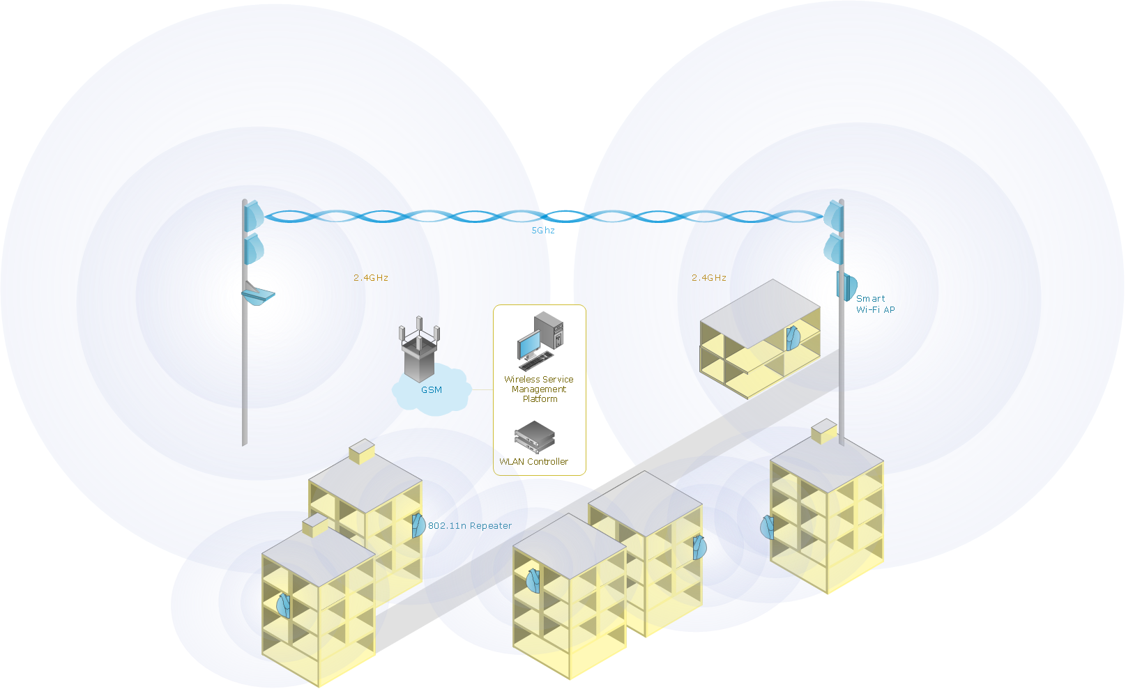
This Cisco logical computer network diagram example was created using the ConceptDraw PRO diagramming and vector drawing software extended with the Cisco Network Diagrams solution from the Computer and Networks area of ConceptDraw Solution Park.
Logical topologies are bound to network protocols and describe how data is moved across the network. ...
EXAMPLE : twisted pair Ethernet is a logical bus topology in a physical star topology layout. while IBM's token ring is a logical ring topology, it is physically set up in star topology." [Logical topology. Wikipedia]
This Cisco logical computer network diagram example was created using the ConceptDraw PRO diagramming and vector drawing software extended with the Cisco Network Diagrams solution from the Computer and Networks area of ConceptDraw Solution Park.
Logical network topology diagram

Star Network Topology


Hybrid Network Topology

Wireless Network Connection
Basic Network Diagram

Virtual networks. Computer and Network Examples

Hotel Network Topology Diagram

- Network Diagram Examples | Real Life Examples Of Bus Topology
- Real Time Example Of Bus Topology
- Practical Example Of Bus Topology
- Real World Example For Mesh And Bus Topology
- Real Life Example Of Ring Topology
- Bus Topology Real Life Example
- Logical network topology diagram | Network Diagram Examples ...
- Example Where Is Ring Topology Used In Common Lif
- Example Of Ring Topology In Real Life
- Example Of Star Topology In Real Life