Bubble diagrams in Landscape Design with ConceptDraw DIAGRAM
Bubble Diagrams are the charts with a bubble presentation of data with obligatory consideration of bubble's sizes. They are analogs of Mind Maps and find their application at many fields, and even in landscape design. At this case the bubbles are applied to illustrate the arrangement of different areas of future landscape design, such as lawns, flowerbeds, playgrounds, pools, recreation areas, etc. Bubble Diagram helps to see instantly the whole project, it is easy for design and quite informative, in most cases it reflects all needed information. Often Bubble Diagram is used as a draft for the future landscape project, on the first stage of its design, and in case of approval of chosen design concept is created advanced detailed landscape plan with specification of plants and used materials. Creation of Bubble Diagrams for landscape in ConceptDraw DIAGRAM software is an easy task thanks to the Bubble Diagrams solution from "Diagrams" area. You can use the ready scanned location plan as the base or create it easy using the special ConceptDraw libraries and templates.
 Event-driven Process Chain Diagrams
Event-Driven Process Chain Diagrams solution extends ConceptDraw DIAGRAM functionality with event driven process chain templates, samples of EPC engineering and modeling the business processes, and a vector shape library for drawing the EPC diagrams and EPC flowcharts of any complexity. It is one of EPC IT solutions that assist the marketing experts, business specialists, engineers, educators and researchers in resources planning and improving the business processes using the EPC flowchart or EPC diagram. Use the EPC solutions tools to construct the chain of events and functions, to illustrate the structure of a business process control flow, to describe people and tasks for execution the business processes, to identify the inefficient businesses processes and measures required to make them efficient.
 SYSML
SYSML
The SysML solution helps to present diagrams using Systems Modeling Language; a perfect tool for system engineering.
HelpDesk
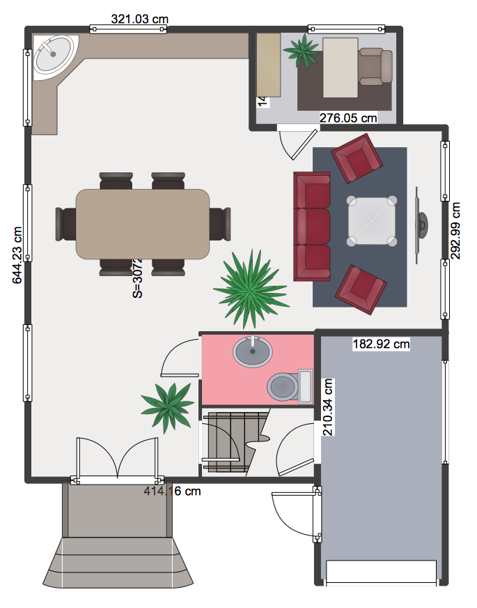
How to Create a Floor Plan
Making a floor plan is the best way to get a handle on how to organize your living space and find out what could be changed. Creating a floor plan to scale is a challenge of the home and interior design process and can be noticeably helpful for visualizing things like furniture layout. You can use ConceptDraw DIAGRAM to produce layouts of real estate properties. ConceptDraw DIAGRAM contains the large quantity of pre-designed vector objects that you can use for quick and easy designing such floor plans. You can easily determine the size of the rooms and distances in your drawing. The ability to create a floor plan is delivered by the Floor Plans solution. This solution extends ConceptDraw DIAGRAM with libraries that contain over 500 objects of floor plan elements. There is a set of special objects that display the sizes, corners, squares and other technical details using the current measurements of units.
 Computer Network Diagrams
Computer Network Diagrams solution extends ConceptDraw DIAGRAM software with samples, templates and libraries of vector icons and objects of computer network devices and network components to help you create professional-looking Computer Network Diagrams, to plan simple home networks and complex computer network configurations for large buildings, to represent their schemes in a comprehensible graphical view, to document computer networks configurations, to depict the interactions between network's components, the used protocols and topologies, to represent physical and logical network structures, to compare visually different topologies and to depict their combinations, to represent in details the network structure with help of schemes, to study and analyze the network configurations, to communicate effectively to engineers, stakeholders and end-users, to track network working and troubleshoot, if necessary.
- Block Diagrams | UML Block Diagram | Functional Block Diagram ...
- Basic Flowchart Symbols and Meaning | SysML block definition ...
- Basic CCTV System Diagram . CCTV Network Diagram Example ...
- What Is Function Diagram
- How to Add a Block Diagram to a MS Word ™ Document Using ...
- Block Diagram Software
- The Organizational Planning Process With Diagram
- How to Add a Bubble Diagram to a PowerPoint Presentation Using ...
- With The Aid Of Diagram Discuss Output Symbol
- Explain The Types Of Connections With Possible Diagram
- Network diagrams with ConceptDraw PRO | UML Diagram | Bubble ...
- Block diagram - Types of individual behavior in organization ...
- Diagrams Of Lan Wan Man Networks
- Payroll process - Swim lane process mapping diagram | Cross ...
- Process Flowchart | Basic Flowchart Symbols and Meaning | Cloud ...
- Information Architecture | Software Development | Control and ...
- Example of DFD for Online Store (Data Flow Diagram ) DFD ...
- Computer System Is Design In Form Of Flow Charting To Help
- Process Flowchart | Cross-Functional Flowchart | Basic Flowchart ...
- Pyramid Diagram | Organizational Structure | Process Flowchart ...

