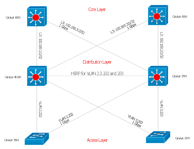
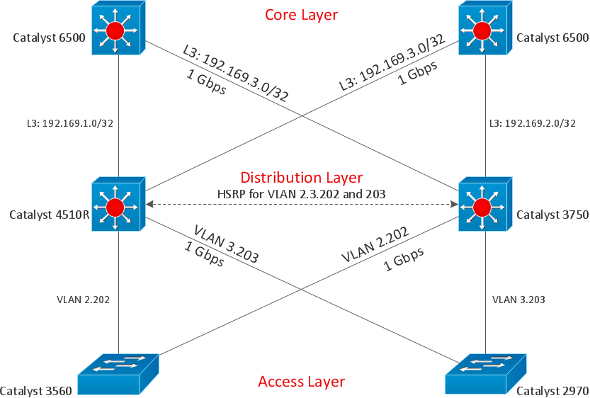
"Cisco Express Forwarding (CEF) is an advanced layer 3 switching technology used mainly in large core networks or the Internet to enhance the overall network performance. Although CEF is a Cisco proprietary protocol other vendors of multi-layer switches or high-capacity routers offer a similar functionality where layer-3 switching or routing is done in hardware (in an ASIC) instead of by software and the (central) CPU." [Cisco Express Forwarding. Wikipedia]
The computer network topology diagram example "Cisco Express Forwarding" was created using the ConceptDraw PRO diagramming and vector drawing software extended with the Cisco Network Diagrams solution from the Computer and Networks area of ConceptDraw Solution Park.
The computer network topology diagram example "Cisco Express Forwarding" was created using the ConceptDraw PRO diagramming and vector drawing software extended with the Cisco Network Diagrams solution from the Computer and Networks area of ConceptDraw Solution Park.
Network topology diagram
ConceptDraw DIAGRAM Database Modeling Software

Draw Diagram on Mac
Cisco Network Templates


"State machine diagram is a behavior diagram which shows discrete behavior of a part of designed system through finite state transitions. State machine diagrams can also be used to express the usage protocol of part of a system. Two kinds of state machines defined in UML 2.4 are:
(1) behavioral state machine, and
(2) protocol state machine.
The following nodes and edges are typically drawn in state machine diagram: behavioral state, behavioral transition, protocol state, protocol transition, different pseudostates. ...
Behavioral state machine is specialization of behavior and is used to specify discrete behavior of a part of designed system through finite state transitions. The state machine formalism used in this case is an object-based variant of Harel statecharts.
Behavior is modeled as a traversal of a graph of state nodes connected with transitions. Transitions are triggered by the dispatching of series of events. During the traversal, the state machine could also execute some activities. ...
Protocol state machine is a specialization of behavioral state machine and is used to express usage protocol or lifecycle of a classifier. It specifies which operations of the classifier can be called in which state and under which condition, thus specifying the allowed call sequences on the classifier’s operations. Protocol state machines express the legal transitions that a classifier can trigger." [uml-diagrams.org/ state-machine-diagrams.html]
The template "UML state machine diagram" for the ConceptDraw PRO diagramming and vector drawing software is included in the Rapid UML solution from the Software Development area of ConceptDraw Solution Park.
www.conceptdraw.com/ solution-park/ software-uml
UML state machine diagram

 Cisco Network Diagrams
Cisco Network Diagrams solution extends ConceptDraw DIAGRAM with the best characteristics of network diagramming software. Included samples, templates and libraries of built-in standardized vector Cisco network icons and Cisco symbols of computers, network devices, network appliances and other Cisco network equipment will help network engineers, network designers, network and system administrators, as well as other IT professionals and corporate IT departments to diagram efficiently the network infrastructure, to visualize computer networks topologies, to design Cisco computer networks, and to create professional-looking Cisco Computer network diagrams, Cisco network designs and schematics, Network maps, and Network topology diagrams in minutes.
- Express -G Diagram | Software and Database Design with ...
- Illustration Area | Illustration | Express -G Diagram | Website Symbols ...
- Gane Sarson Diagram | Event-driven Process Chain Diagrams EPC ...
- Software and Database Design with ConceptDraw PRO | PM Easy ...
- Cisco Express Forwarding - Network topology diagram | Cisco ...
- Cisco Network Topology | Cisco Express Forwarding - Network ...
- Express -G Diagram | UML Class Diagram Notation | Types of ...
- Cisco Express Forwarding network topology diagram | Roaming ...
- Cisco Express Forwarding - Network topology diagram
- ERD Symbols and Meanings | Entity Relationship Diagram Symbols ...
- How To use Switches in Network Diagram | Cisco Network ...
- UML Diagram
- Data Flow Diagrams
- COM and OLE Diagram | Block Diagrams | Software Diagram ...
- Data Flow Diagrams with ConceptDraw PRO
- DFD Library System | Data Flow Diagram Symbols. DFD Library ...
- Data structure diagram with ConceptDraw PRO | Bubble diagrams ...
- Data Flow Diagrams
- Entity-Relationship Diagram
- Gane Sarson Diagram | Universal Diagramming Area | Data ...