 Fishbone Diagram
Fishbone Diagrams solution extends ConceptDraw PRO software with templates, samples and library of vector stencils for drawing the Ishikawa diagrams for cause and effect analysis.
 Fishbone Diagrams
The Fishbone Diagrams solution extends ConceptDraw PRO v10 software with the ability to easily draw the Fishbone Diagrams (Ishikawa Diagrams) to clearly see the cause and effect analysis and also problem solving. The vector graphic diagrams produced using this solution can be used in whitepapers, presentations, datasheets, posters, and published technical material.
HelpDesk
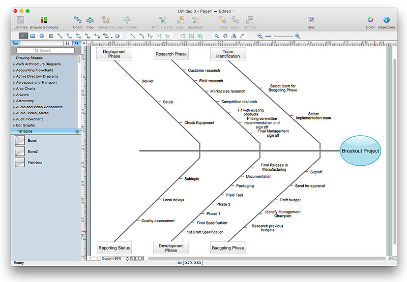
How to Draw a Fishbone Diagram with ConceptDraw PRO
Fishbone (Ishikawa) Diagram is often used in business to determine the cause of some problem. A Fishbone diagram is also called cause-and-effect diagram.The main goal of the Fishbone diagram is to illustrate in a graphical way the relationship between a given outcome and all the factors that influence this outcome. The complete diagram resembles a fish skeleton as its name implies. Cause and Effect analysis is used in management to identify the possible causes of a problem in order to eliminate them. The ability to create a Fishbone Diagram is supported by the Fishbone Diagram solution.
 Interactive Voice Response Diagrams
Interactive Voice Response Diagrams solution extends ConceptDraw PRO v10 software with samples, templates and libraries of ready-to-use vector stencils that help create Interactive Voice Response (IVR) diagrams illustrating in details a work of interactive voice response system, the IVR system’s logical and physical structure, Voice-over-Internet Protocol (VoIP) diagrams, and Action VoIP diagrams with representing voice actions on them, to visualize how the computers interact with callers through voice recognition and dual-tone multi-frequency signaling (DTMF) keypad inputs.
- Fishbone Diagram For Customer Service
- Fishbone Diagram Example For Service Industry
- Block diagram - Gap model of service quality | Taxi Service Data ...
- Fishbone Diagram Bad Customer Service Fishbone Diagram Bad
- Fishbone Diagram | Service 4 Ss fishbone diagram - Template ...
- Fishbone Diagrams | Total Quality Management Value | Service 4 Ss ...
- Service 8 Ps fishbone diagram - Template | Fishbone Diagram ...
- Fishbone Diagram Example | Fishbone Diagram Problem Solving ...
- The Fish Bone Diagram In Service Marketing
- Total Quality Management Value | Fishbone Diagram Procedure ...
- Fish Bone Analysis For Customer Complaints
- Fishbone Diagram | Leaky bucket diagram | Service -goods ...
- Service -goods continuum diagram | How To create Diagrams for ...
- Manufacturing 8 Ms fishbone diagram - Template | How Do ...
- Cause and Effect Analysis - Fishbone Diagrams for Problem Solving ...
- Business Service Diagram
- Service 8 Ps fishbone diagram - Template
- Fishbone Diagram | Fishbone Diagram Example | Cause and Effect ...
- Cause and Effect Analysis - Fishbone Diagrams for Problem Solving ...
- Fishbone Diagram Template | Total Quality Management Value ...
