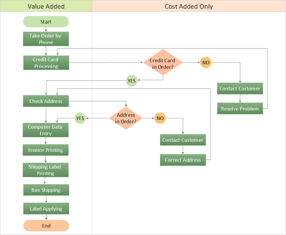
How to Create a Cross Functional Flow Chart
If neither of 45 vector shapes of the Cross-Functional Flowcharts solution don't fit your needs, you will want to learn How to create a unique Cross-Functional flowchart. ConceptDraw Arrows10 Technology - This is more than enough versatility to draw any type of diagram with any degree of complexity. Drawing software lets you to make horizontal and vertical, audit, opportunity and many more flowcharts.
 Business Process Mapping
The Business Process Mapping solution for ConceptDraw PRO is for users involved in process mapping and creating SIPOC diagrams.
"A piping and instrumentation diagram/ drawing (P&ID) is a diagram in the process industry which shows the piping of the process flow together with the installed equipment and instrumentation. ...
P&IDs play a significant role in the maintenance and modification of the process that it describes. It is critical to demonstrate the physical sequence of equipment and systems, as well as how these systems connect. During the design stage, the diagram also provides the basis for the development of system control schemes, allowing for further safety and operational investigations, such as a Hazard Analysis and Operability Study...
For processing facilities, it is a pictorial representation of:
Key piping and instrument details,
Control and shutdown schemes,
Safety and regulatory requirements,
Basic start up and operational information." [Piping and instrumentation diagram. Wikipedia]
The piping and instrumentation diagram template for the ConceptDraw PRO diagramming and vector drawing software is included in the Chemical and Process Engineering solution from the Engineering area of ConceptDraw Solution Park.
- Process Flow Diagram Symbols | Process and Instrumentation ...
- Interior Design Site Plan - Design Elements | Block Diagram Creator ...
- Fitter Diagrams
- Process Flow Diagram Symbols | Home Electrical Plan | Electrical ...
- Diagram Of 3bedroom With Electrical Fitting
- Pipe Fitting Schematics
- How To use House Electrical Plan Software | Electricity Fitting Diagram
- House Electrical Plan Software. Electrical Diagram Software | Home ...
- Mechanical Fitter Diagram
- Pipes Fitting Material Diagram And Uses
- Process Flow Diagram Symbols | Chemical Engineering | Process ...
- Fitter Trade Related Symbols
- Electrical Diagram Software | Process Flowchart | Electrical Besic ...
- Pipe Fitting In Chemical Engineering
- Fitter Engineering Drawing Diagram
- House Electrical Light Fitting Casing In Room Diagram
- Process Flowchart | Fitting Symbol Function In Chemical Engineering
- Electrical Switch Board Fitting Video Download
- Piping and Instrumentation Diagram Software | Design elements ...
- Examples Of Fitting Symbols With Diagrams

-piping-and-instrumentation-diagram-template.png--diagram-flowchart-example.png)