Electrical Symbols — Resistors
A resistor is a passive two-terminal electrical component that implements electrical resistance as a circuit element. Resistors may be used to reduce current flow, and, at the same time, may act to lower voltage levels within circuits. In electronic circuits, resistors are used to limit current flow, to adjust signal levels, bias active elements, and terminate transmission lines among other uses. Fixed resistors have resistances that only change slightly with temperature, time or operating voltage. Variable resistors can be used to adjust circuit elements (such as a volume control or a lamp dimmer), or as sensing devices for heat, light, humidity, force, or chemical activity. 26 libraries of the Electrical Engineering Solution of ConceptDraw DIAGRAM make your electrical diagramming simple, efficient, and effective. You can simply and quickly drop the ready-to-use objects from libraries into your document to create the electrical diagram.Wiring Diagrams with ConceptDraw DIAGRAM
A Wiring Diagram is a comprehensive schematic that depicts the electrical circuit system, shows all the connectors, wiring, signal connections (buses), terminal boards between electrical or electronic components and devices of the circuit. Wiring Diagram illustrates how the components are connected electrically and identifies the wires by colour coding or wire numbers. These diagrams are necessary and obligatory for identifying and fixing faults of electrical or electronic circuits, and their elimination. For designing Wiring Diagrams are used the standardized symbols representing electrical components and devices. ConceptDraw Solution Park offers the Electrical Engineering solution from the Engineering area with 26 libraries of graphics design elements and electrical schematic symbols for easy drawing various Wiring Diagrams, Electrical Circuit and Wiring Blueprints, Electrical and Telecom schematics of any complexity, Electrical Engineering Diagrams, Power Systems Diagrams, Repair Diagrams, Maintenance Schemes, etc. in ConceptDraw DIAGRAM software.Mechanical Drawing Software
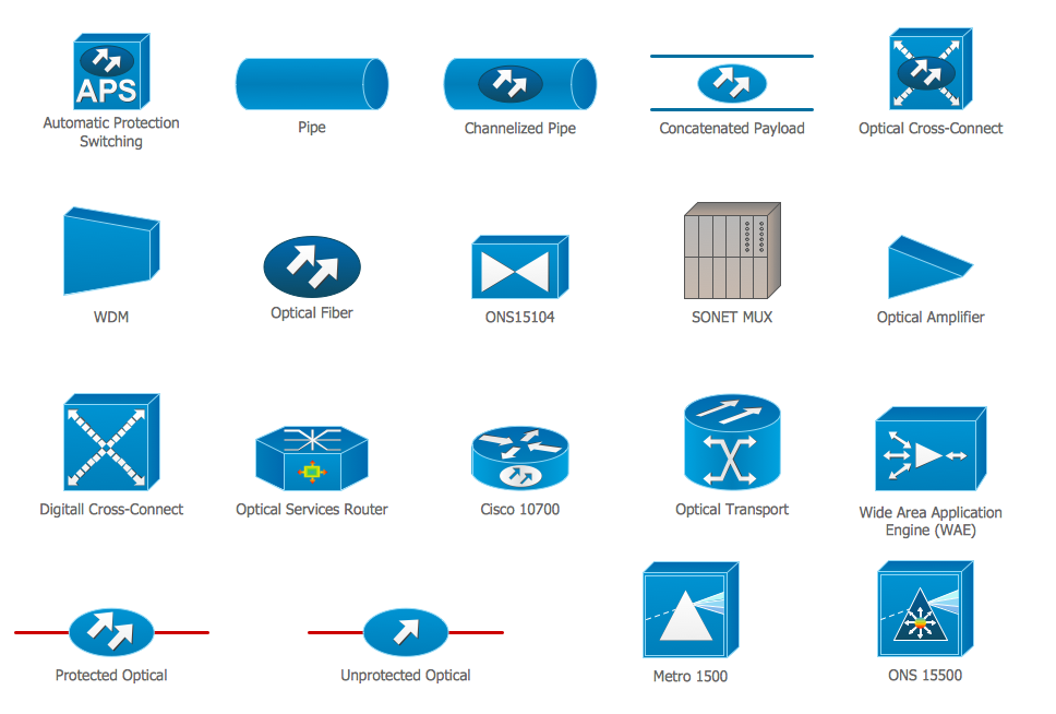
It is impossible to imagine mechanical engineering without drawings which represent various mechanical schemes and designs. ConceptDraw DIAGRAM diagramming and vector drawing software supplied with Mechanical Engineering solution from the Engineering area of ConceptDraw Solution Park offers the set of useful tools which make it a powerful Mechanical Drawing Software.Cisco Optical. Cisco icons, shapes, stencils and symbols
The ConceptDraw vector stencils library Cisco Optical contains symbols for drawing the computer network diagrams.- How To use House Electrical Plan Software | Process Flowchart ...
- Electrical Symbols, Electrical Schematic Symbols | HR Flowcharts ...
- Bio Flowchart Lite | Accounting Flowchart Symbols | Functional ...
- Design elements - Delay elements | Basic Flowchart Symbols and ...
- Design elements - Resistors | Resistors - Vector stencils library ...
- Design elements - Resistors | Resistors - Vector stencils library ...
- Swim Lane Flowchart Symbols | Technical Drawing Software ...
- Simple Flow Chart | LLNL Flow Charts | Sales Process Flowchart ...
- Entity Relationship Diagram Symbols | Mechanical Drawing ...
- Basic Flowchart Symbols and Meaning | ERD Symbols and ...
- Design elements - Chemical engineering | Process Engineering ...
- Mechanical Drawing Symbols | Process Flowchart | Technical ...
- Design elements - Semiconductor diodes | Accounting Flowchart ...
- Electrical Symbols — Resistors | Design elements - Astronomical ...
- Current Flow Diagrams For The Electrical Circuits
- Resistor Symbols With Examples
- Electrical Symbols — Resistors | How To use House Electrical Plan ...
- Design elements - Resistors
- Electrical Symbols, Electrical Diagram Symbols | Anyone Have an ...
- Electrical Drawing Software and Electrical Symbols | Wiring ...


