 Network Layout Floor Plans
Network Layout Floor Plans solution extends ConceptDraw DIAGRAM software functionality with powerful tools for quick and efficient documentation the network equipment and displaying its location on the professionally designed Network Layout Floor Plans. Never before creation of Network Layout Floor Plans, Network Communication Plans, Network Topologies Plans and Network Topology Maps was not so easy, convenient and fast as with predesigned templates, samples, examples and comprehensive set of vector design elements included to the Network Layout Floor Plans solution. All listed types of plans will be a good support for the future correct cabling and installation of network equipment.
Home Networking
Network Mapper
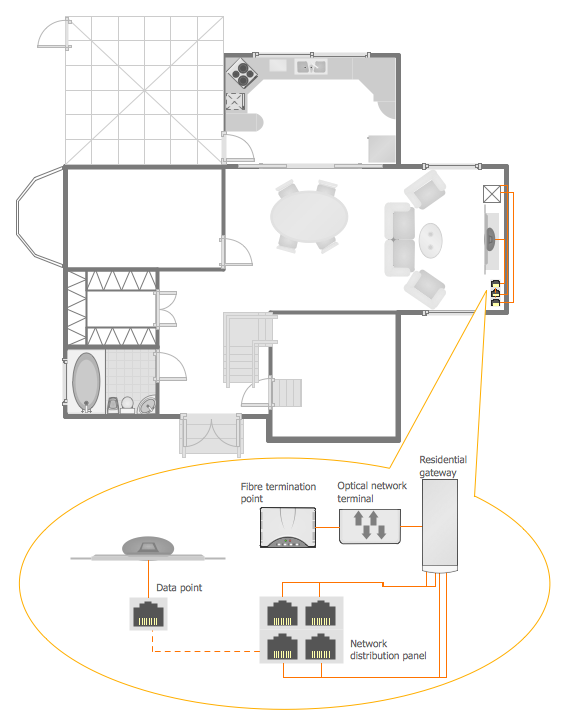
This network layout floorplan example was drawn on the base of the picture "Ethernet cable layout" illustrating "UGA Technical Network Liaison Handbook" from the website of the University of Georgia.
[netinfo.uga.edu/ tnlhand/ landiag.gif]
"The Ethernet physical layer is the physical layer component of the Ethernet family of computer network standards.
The Ethernet physical layer evolved over a considerable time span and encompasses quite a few physical media interfaces and several magnitudes of speed. The speed ranges from 1 Mbit/ s to 100 Gbit/ s, while the physical medium can range from bulky coaxial cable to twisted pair and optical fiber. In general, network protocol stack software will work similarly on all physical layers.
10-gigabit Ethernet was already used in both enterprise and carrier networks by 2007, with 40 Gbit/ s and 100 Gbit/ s Ethernet ratified." [Ethernet physical layer. Wikipedia]
The network layout floorplan example "Ethernet cable layout" was created using the ConceptDraw PRO diagramming and vector drawing software extended with the Network Layout Floor Plans solution from the Computer and Networks area of ConceptDraw Solution Park.
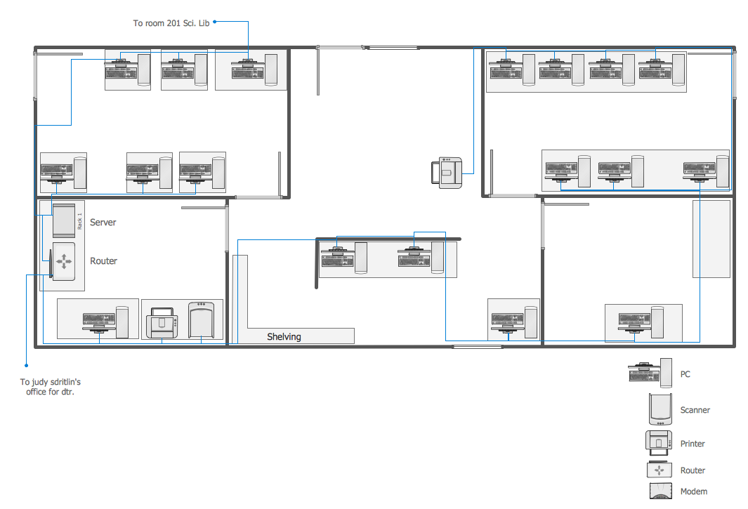
Network layout floorplan

"The Ethernet physical layer is the physical layer component of the Ethernet family of computer network standards.
The Ethernet physical layer evolved over a considerable time span and encompasses quite a few physical media interfaces and several magnitudes of speed. The speed ranges from 1 Mbit/ s to 100 Gbit/ s, while the physical medium can range from bulky coaxial cable to twisted pair and optical fiber. In general, network protocol stack software will work similarly on all physical layers.
10-gigabit Ethernet was already used in both enterprise and carrier networks by 2007, with 40 Gbit/ s and 100 Gbit/ s Ethernet ratified. ...
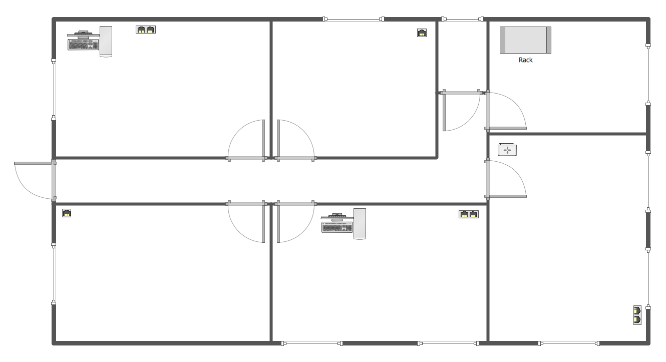
Many Ethernet adapters and switch ports support multiple speeds, using autonegotiation to set the speed and duplex for the best values supported by both connected devices. If auto-negotiation fails, a multiple-speed device will sense the speed used by its partner, but will assume half-duplex. A 10/ 100 Ethernet port supports 10BASE-T and 100BASE-TX. A 10/ 100/ 1000 Ethernet port supports 10BASE-T, 100BASE-TX, and 1000BASE-T." [Ethernet physical layer. Wikipedia]
The LAN equipment and cabling layout floorplan example "Ethernet local area network layout floor plan" was created using the ConceptDraw PRO diagramming and vector drawing software extended with the Network Layout Floor Plans solution from the Computer and Networks area of ConceptDraw Solution Park.
The Ethernet physical layer evolved over a considerable time span and encompasses quite a few physical media interfaces and several magnitudes of speed. The speed ranges from 1 Mbit/ s to 100 Gbit/ s, while the physical medium can range from bulky coaxial cable to twisted pair and optical fiber. In general, network protocol stack software will work similarly on all physical layers.
10-gigabit Ethernet was already used in both enterprise and carrier networks by 2007, with 40 Gbit/ s and 100 Gbit/ s Ethernet ratified. ...
Many Ethernet adapters and switch ports support multiple speeds, using autonegotiation to set the speed and duplex for the best values supported by both connected devices. If auto-negotiation fails, a multiple-speed device will sense the speed used by its partner, but will assume half-duplex. A 10/ 100 Ethernet port supports 10BASE-T and 100BASE-TX. A 10/ 100/ 1000 Ethernet port supports 10BASE-T, 100BASE-TX, and 1000BASE-T." [Ethernet physical layer. Wikipedia]
The LAN equipment and cabling layout floorplan example "Ethernet local area network layout floor plan" was created using the ConceptDraw PRO diagramming and vector drawing software extended with the Network Layout Floor Plans solution from the Computer and Networks area of ConceptDraw Solution Park.
Ethernet LAN layout floorplan

Network Diagram Software. LAN Network Diagrams. Physical Office Network Diagrams


Home area networks (HAN). Computer and Network Examples

The vector stencils library "Network layout floorplan" contain 34 symbol icons for drawing computer network floor plans, communication equipment layouts, and structured cabling diagrams.
"Structured cabling is building or campus telecommunications cabling infrastructure that consists of a number of standardized smaller elements (hence structured) called subsystems. ...
Structured cabling design and installation is governed by a set of standards that specify wiring data centers, offices, and apartment buildings for data or voice communications using various kinds of cable, most commonly category 5e (CAT-5e), category 6 (CAT-6), and fibre optic cabling and modular connectors. These standards define how to lay the cabling in various topologies in order to meet the needs of the customer, typically using a central patch panel (which is normally 19 inch rack-mounted), from where each modular connection can be used as needed. Each outlet is then patched into a network switch (normally also rack-mounted) for network use or into an IP or PBX (private branch exchange) telephone system patch panel." [Structured cabling. Wikipedia]
The design elements example "Network layout floorplan - Vector stencils library" was created using the ConceptDraw PRO diagramming and vector drawing software extended with the Network Layout Floor Plans solution from the Computer and Networks area of ConceptDraw Solution Park.
PC

Scanner

Switch

Router

Modem

Hub

Rack Mount

Printer

Floor Mounted Outlet

Single Outlet

Duplex Outlet

Direct bus cable

Tops or bottoms bus cable

Side to side bus cable

Multi-tree bus cable

Bottom to side bus cable

Sides bus cable

Door

Door, threshold

Door, stop

Door, stop, threshold

Door, frame

Door, frame, threshold

Door, frame, stop

Door, frame, stop, threshold

Window

Window, sill

Window, sash

Window, sash, sill

Window, frame

Window, frame, sill

Window, frame, sash

Window, frame, sash, sill

HelpDesk
How to Add a Rack Diagram to MS Word Document
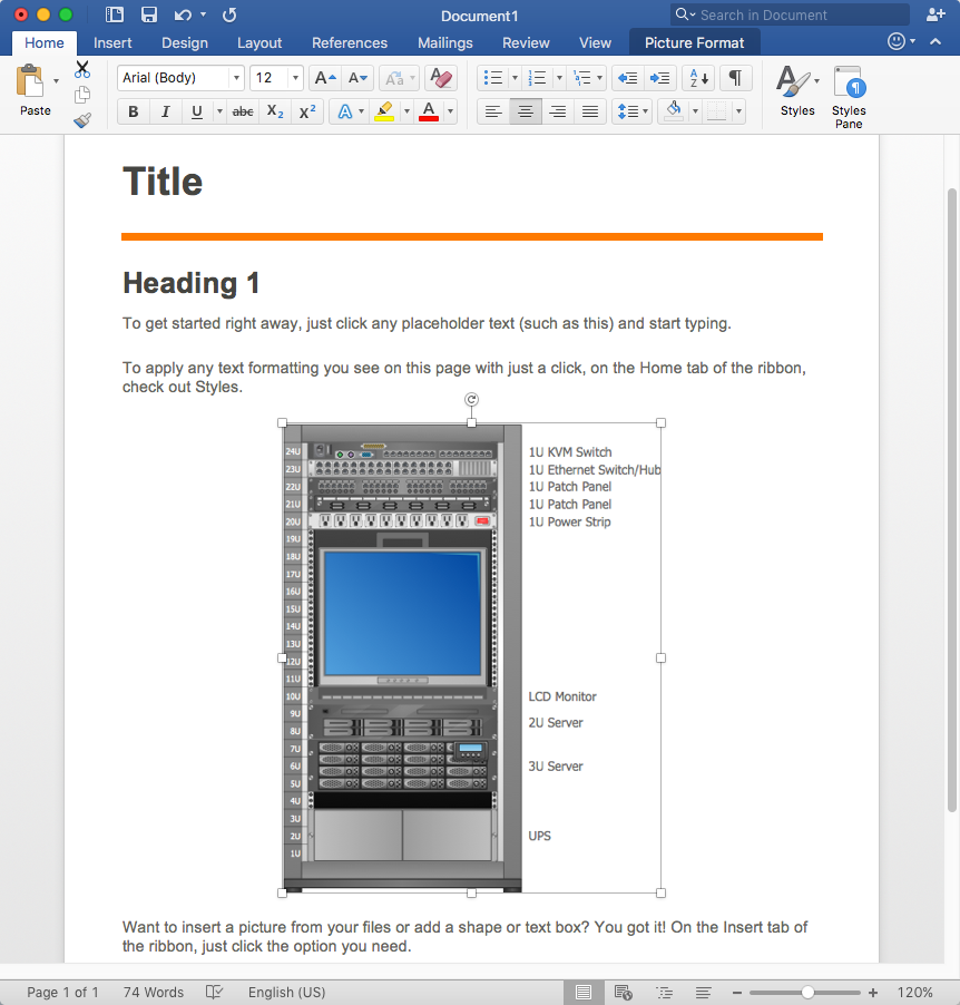
Network Diagramming Software for Design Rack Diagrams
_Win_Mac.png)
Network Diagramming Software for Network Active Directory Diagrams
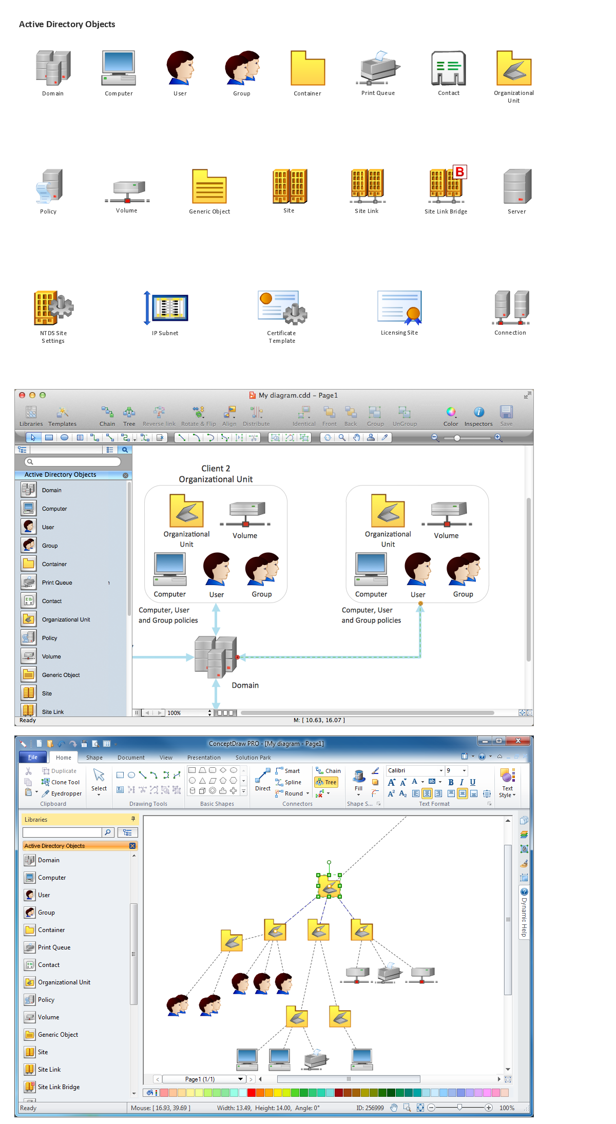
Network Components
 Computer and Networks Area
The solutions from Computer and Networks Area of ConceptDraw Solution Park collect samples, templates and vector stencils libraries for drawing computer and network diagrams, schemes and technical drawings.
Network Layout

- Network Layout Floor Plans | Ethernet cable layout | Home ...
- Ethernet cable layout | Network Layout Floor Plans | Network layout ...
- Network Layout Floor Plans | ConceptDraw PRO Network Diagram ...
- Network Layout Floor Plans | Design elements - Network layout ...
- Ethernet local area network layout floor plan | Ethernet cable layout ...
- Ethernet cable layout | Network wiring cable. Computer and Network ...
- Network Layout Floor Plans | Network Diagram Software LAN ...
- Network Layout Floor Plans | Network Diagram Software LAN ...
- Network Layout Floor Plans | Floor Plans | How to Add a Rack ...
- Network Layout Floor Plans | Network layout floorplan - Vector ...
- Network Layout Floor Plans | Network Diagram Software LAN ...
- Network Layout Floor Plans | Ethernet local area network layout floor ...
- Network Layout Floor Plans | Design elements - Network layout ...
- Network Cable Installation Plan Floor Layout
- Network Layout Floor Plans | Network Diagram Software LAN ...
- How to Draw a Floor Plan for Your Office | How to Resize Objects in ...
- Router Floor Plan
- Ethernet network | Ethernet local area network layout floor plan ...
- Network Layout Floor Plans | Network Layout | Design elements ...