 Healthcare Management Workflow Diagrams
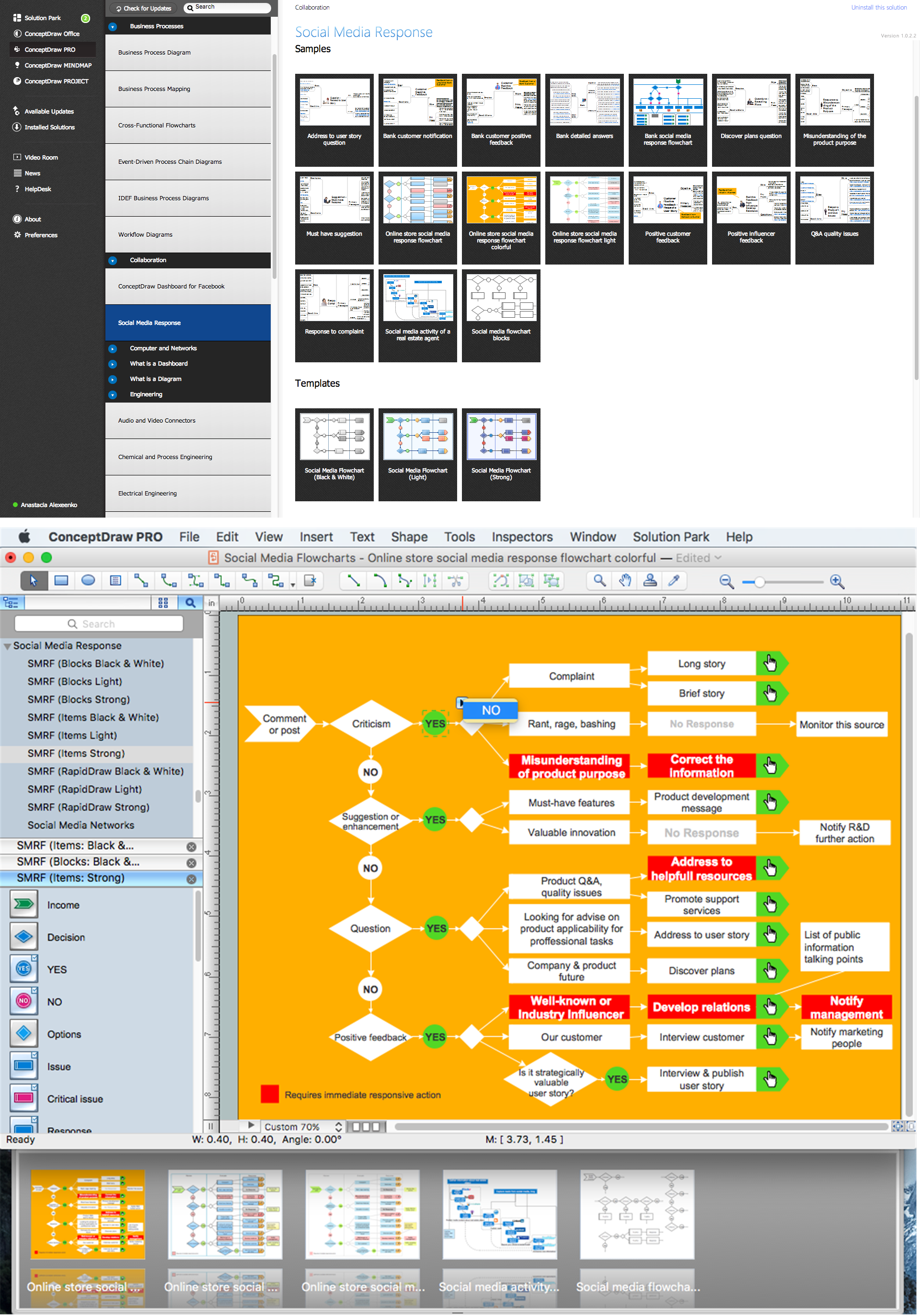
Healthcare Management Workflow Diagrams solution contains large set of colorful samples and libraries with predesigned vector pictograms and symbols of health, healthcare equipment, medical instruments, pharmaceutical tools, transport, medication, departments of healthcare organizations, the medical icons of people and human anatomy, as well as the predesigned flowchart objects, connectors and arrows, which make it the best for designing clear and comprehensive Medi?al Workflow Diagrams and Block Diagrams, Healthcare Management Flowcharts and Infographics, Healthcare Workflow Diagram, for depicting the healthcare workflow and clinical workflows in healthcare, for making the workflow analysis healthcare and healthcare workflow management.
Types of Flowcharts


Flowchart Marketing Process. Flowchart Examples

Structured Systems Analysis and Design Method (SSADM) with ConceptDraw DIAGRAM

Diagramming Software for Design UML Timing Diagrams


Basic Flowchart Symbols and Meaning


What is Interactive Flowcharts
Data Flow Diagram

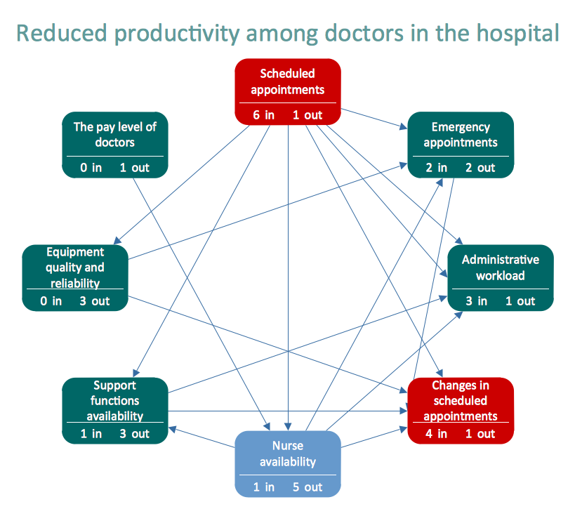
Relationships Analysis

Flowchart on Bank. Flowchart Examples


- Types of Flowchart - Overview | DFD Library System | Types of ...
- Hospital Flowchart Diagram
- Activity Diagram For Hospital Management System With Swimlane
- Types of Flowcharts | DFD Library System | Types of Flowchart ...
- Line Graphs | Business Process Diagrams | Hospital Workflow ...
- Flow Chart Of Hospital Management System
- IDEF9 Standard | IDEF Business Process Diagrams | Hospital ...
- Types of Flowcharts | Types of Flowchart - Overview | Local area ...
- Data Flow Diagram For Hospital Management System Level 0
- Data Flow Diagram For Hospital Appointment System