Data Flow Diagram Model
Data Flow Diagram (DFD) is a technique of graphical structural analysis, describing the sources external to the system, recipients of data, also logical functions, data flows and data stores that are accessed. The DFD's goal is to show how each process converts its inputs into the outputs and to identify relationships between these processes, at this make the system's description clear and understandable at every level of detail. Historically happened that for describing Data Flow Diagrams are used two notations - Yourdon and Gane-Sarson that differ each from other by graphical representation of symbols. The DFD model, like most other structural models is a hierarchical model. Each process can be subjected to decomposition on the structural components, the relationships between which in the same notation can be shown on a separate diagram. Typically, several DFD models are built when modeling the system. ConceptDraw DIAGRAM software enhanced with Data Flow Diagrams solution ideally suits for creation DFD models and professional drawing Data Flow Diagrams.ConceptDraw DIAGRAM : Able to Leap Tall Buildings in a Single Bound
ConceptDraw DIAGRAM is the world’s premier cross-platform business-diagramming tool. Many, who are looking for an alternative to Visio, are pleasantly surprised with how well they can integrate ConceptDraw DIAGRAM into their existing processes. With tens of thousands of template objects, and an easy method for importing vital custom objects from existing Visio documents, ConceptDraw DIAGRAM is a powerful tool for making extremely detailed diagrams, quickly and easily.Project —Task Trees and Dependencies
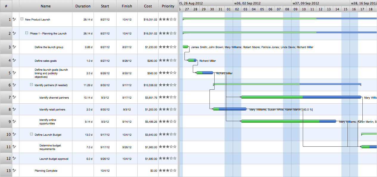
Users new to ConceptDraw PROJECT will find the Basic lessons an essential platform for familiarizing themselves with the program′s functions. This video lesson will teach you how to set up task trees and dependencies.UML Use Case Diagram Example. Social Networking Sites Project
UML Diagrams Social Networking Sites Project. This sample was created in ConceptDraw DIAGRAM diagramming and vector drawing software using the UML Use Case Diagram library of the Rapid UML Solution from the Software Development area of ConceptDraw Solution Park. This sample shows the Facebook Socio-health system and is used at the projection and creating of the social networking sites.- Customer Complaint Service Flow Chart
- Data Flow Diagram Customer Complaint
- Process Flowchart | Basic Flowchart Symbols and Meaning | Basic ...
- Block diagram - Gap model of service quality | Taxi Service Data ...
- Work Order Process Flowchart . Business Process Mapping ...
- Basic Flowchart Symbols and Meaning | Example of DFD for Online ...
- Stakeholder Onion Diagrams | Simple Flow Chart | SWOT analysis ...
- Providing telecom services - Cross-functional flowchart | Business ...
- Basic Flowchart Symbols and Meaning | Process Flowchart ...
- Bank Sequence Diagram | UML use case diagram - Banking system ...
- Example of DFD for Online Store (Data Flow Diagram) DFD ...
- Courier Company Process Chart
- Top 5 Android Flow Chart Apps | Technical Flow Chart | Online Flow ...
- Data Flow Diagram Symbols. DFD Library | Example of DFD for ...
- Fish Bone Analysis For Customer Complaints
- Example of DFD for Online Store (Data Flow Diagram) DFD ...
- Bank Detailed Answers | Bank Customer Positive Feedback | Bank ...
- Marketing program - Infographics | Competitor Analysis | Marketing ...
- The Means to Respond to Social Media Mentions | Bank Customer ...
- Concept Map | Misunderstanding Product Purpose | How to Draw a ...


