Flowchart on Bank. Flowchart Examples


UML Use Case Diagram Example. Services UML Diagram. ATM system

Model Based Systems Engineering

 ATM UML Diagrams
The ATM UML Diagrams solution lets you create ATM solutions and UML examples. Use ConceptDraw DIAGRAM as a UML diagram creator to visualize a banking system.
IDEF0 Flowchart Symbols

Software Diagram Examples and Templates

UML for Bank

UML Component Diagram


UML Sequence Diagram

Near field communication (NFC). Computer and Network Examples


UML Activity Diagram

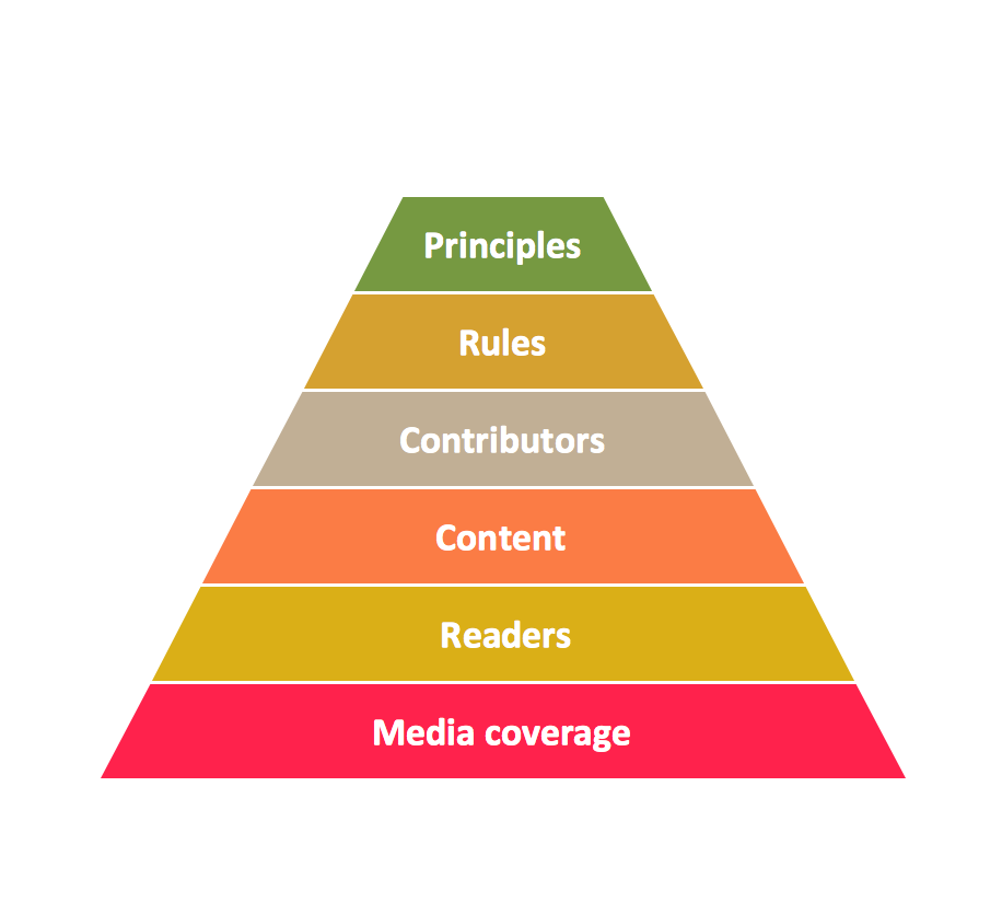
Pyramid Diagram
Basic Audit Flowchart. Flowchart Examples
Check Order Process Flowchart. Flowchart Examples
- Atm Flowchart Example
- Flowchart Modeling For Cash Withdrawal Transaction Using Atm
- ATM Solutions | UML Sequence Diagram | Swim Lane Flowchart ...
- Account Flowchart Stockbridge System. Flowchart Examples | UML ...
- Ppt On Flowchart To Depict The Working Of An Atm Machine
- Flowchart Marketing Process. Flowchart Examples | UML Flowchart ...
- Cross-Functional Flowcharts | ATM Solutions | UML Use Case ...
- ATM Solutions | Account Flowchart Stockbridge System. Flowchart ...
- UML Deployment Diagram Example - ATM System UML diagrams ...
- Flowchart on Bank. Flowchart Examples | How to Create a Bank ...
- Draw A Flowchart How To Atm Machine Works
- Atm Cash Withdrawal Steps In A Flow Chart Pic
- Bank UML Diagram | ATM UML Diagrams | Account Flowchart ...
- Flowchart Marketing Process. Flowchart Examples | Account ...
- Process Flowchart | UML Use Case Diagram Example . Services ...
- Flowchart Examples and Templates | Bubble Diagrams | ATM UML ...
- Sales Process Flowchart . Flowchart Examples | Atm Stateflow
- ATM UML Diagrams | Flowchart on Bank. Flowchart Examples ...
- UML Use Case Diagram Example . Services UML Diagram. ATM ...
- Flowchart For Cash Withdrawal From Atm