HelpDesk
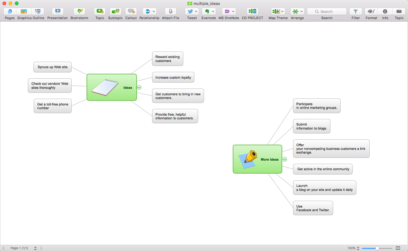
How to Operate a Multiple Main Idea on Your Mind Map
If you are using multiple Main Ideas your maps, it is necessary to know that there is a difference in behavior between the original primary Main Idea and the other Ideas you add.UML Flowchart Symbols
The UML diagram is a powerful tool which lets visually represent all system's components, the interactions between them and relationships with external user interface. The Rapid UML solution for ConceptDraw PRO software offers diversity of UML flowchart symbols for drawing all types of UML diagrams.Types of Flowcharts
A Flowchart is a graphical representation of process, algorithm, workflow or step-by-step solution of the problem. It shows the steps as boxes of various kinds and connects them by arrows in a defined order depicting a flow. There are twelve main Flowchart types: Basic Flowchart, Business Process Modeling Diagram (BPMN), Cross Functional Flowchart, Data Flow Diagram (DFD), IDEF (Integrated DEFinition) Flowchart, Event-driven Process Chain (EPC) Diagram, Influence Diagram (ID), Swimlane Flowchart, Process Flow Diagram (PFD), Specification and Description Language (SDL) Diagram, Value Stream Mapping, Workflow Diagram. Using the Flowcharts solution from the Diagrams area of ConceptDraw Solution Park you can easy and quickly design a Flowchart of any of these types. This solution offers a lot of special predesigned vector symbols for each of these widely used notations. They will make the drawing process of Flowcharts much easier than ever. Pay also attention for the included collection of ready Flowchart examples, samples and quick-start templates. This is business process improvement tools. If you are looking for MS Visio for your Mac, then you are out of luck, because it hasn't been released yet. However, you can use Visio alternatives that can successfully replace its functions. ConceptDraw PRO is an alternative to MS Visio for Mac that provides powerful features and intuitive user interface for the same.
SDL Flowchart Symbols
Drawing the diagrams we try to find in help the powerful software and now we have the ConceptDraw PRO. The ability easily create the SDL diagrams is made possible thanks to unique Specification and Description Language (SDL) Solution from the Industrial Engineering Area of ConceptDraw Solution Park. This solution extends ConceptDraw PRO 2 libraries - SDL Connectors and SDL Diagrams that contain 70 predesigned SDL flowchart symbols.HelpDesk
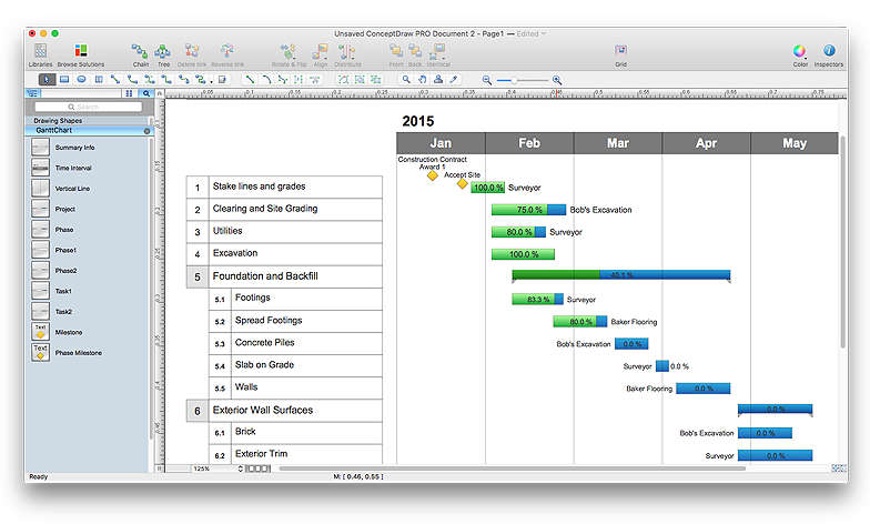
How to Draw a Gantt Chart Using ConceptDraw PRO
A Gantt chart is intended to provide a visualization of a project schedule. It is developed to help planning, coordinating, and tracking on project tasks implementation. One of the most critical resources for a project implementation is a time resources. Gantt chart - is one of the most convenient and popular way of graphical representation of a project tasks progress in conjunction with the corresponding time consumption. Gantt chart's function is to show project tasks completion in a progress, and to make a project manager sure that project tasks were completed on time. ConceptDraw Office is a clear and easy-to-use tool for project management. It is a very handy visual tool that helps make a project processing clear.Product Overview
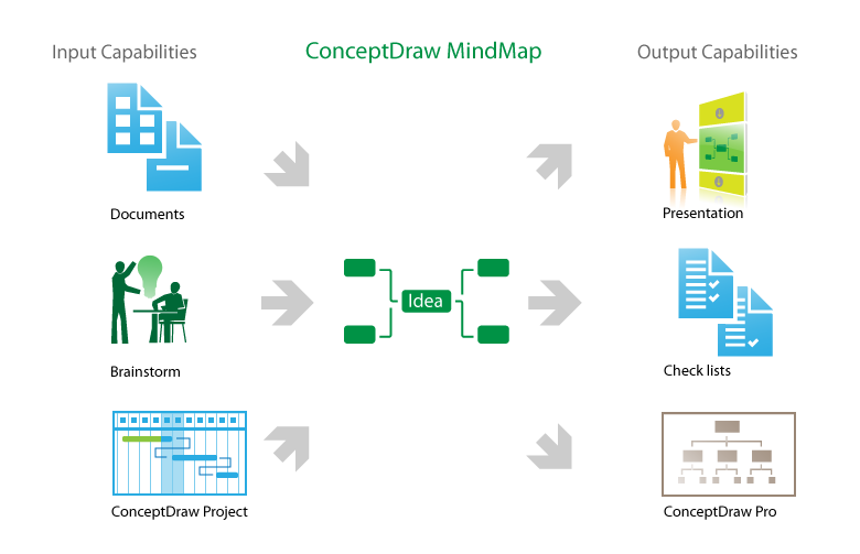
The role of ConceptDraw MINDMAP is to organize and plan idea development and communicate between process participants. Mind maps are convenient to prepare presentations for team and management and send task lists and related information.
 Specification and Description Language (SDL)
For people in the field of systems engineering or system design, working with specification and description language (sdl) and finite state machines (fsm).
- Multiple Inheritance In Uml Diagram Example
- Multi Layer Venn Diagram. Venn Diagram Example | Venn ...
- Uml Inheritance Example
- Inheritance Example In Uml
- Mathematical Diagrams | Basic Flowchart Symbols and Meaning ...
- Process Flowchart | Design elements - Bank UML sequence ...
- Basic Flowchart Symbols and Meaning | Process Flowchart | Flow ...
- Pyramid Diagram | Flowchart design. Flowchart symbols, shapes ...
- Telecommunication Network Diagrams | Process Flowchart | SDL ...
- UML Flowchart Symbols | UML Class Diagram Notation | UML ...
- Process Flowchart | How to Draw an Organization Chart | Venn ...
- Process Flowchart | Structured Systems Analysis and Design ...
- UML Flowchart Symbols | Design elements - UML activity diagrams ...
- Basic Flowchart Symbols and Meaning | Block Diagram | Electrical ...
- Process Flowchart | UML Diagram Types List | Data Flow Diagram ...
- Top 5 Android Flow Chart Apps | Program Structure Diagram | Data ...
- ConceptDraw PRO ER Diagram Tool | ER Diagram for Cloud ...
- Process Flowchart | ConceptDraw Arrows10 Technology | How To ...
- Controls - Vector stencils library | Process Flowchart | Interior Design ...
- Business Process Modeling Notation Template | Business Process ...


