Circuits and Logic Diagram Software
Circuit diagram is a graphical representation of electrical circuits, wire connections between devices, among them power and signal connections. Circuit diagrams are successfully used during design, construction and maintenance of different electrical and electronic equipment, and also for visualizing expressions using a boolean algebra in the computer science. These diagrams don't show a physical arrangement of components. One of advanced application of ConceptDraw DIAGRAM software is electrical engineering. Included to ConceptDraw Solution Park, Electrical Engineering solution from the Engineering area offers templates, samples and incredibly large quantity of vector design elements of circuits and logic symbols, which are helpful for professional drawing Circuit diagrams, Logic circuit diagrams, Wiring diagrams, Electrical schematics, Digital and Analog logic designs, Integrated circuit schematics, Circuit board and Amplifier diagrams, Power systems diagrams, Maintenance and Repair diagrams of any difficulty.Fault Tree Analysis Software
ConceptDraw DIAGRAM extended with Fault Tree Analysis Diagrams Solution from the Industrial Engineering Area of ConceptDraw Solution Park is the best Fault Tree Analysis Software. First of all, Fault Tree Analysis Diagrams Solution provides a set of samples which are the good examples of easy drawing professional looking Fault Tree Analysis Diagrams.Interior Design. Shipping and Receiving — Design Elements
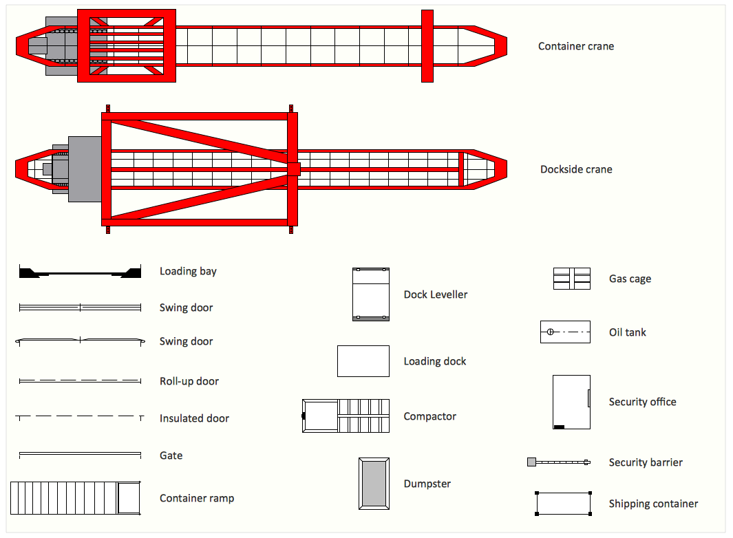
Create port terminal plans use the appropriate stencils with shipping and receiving design element.ConceptDraw DIAGRAM
ConceptDraw DIAGRAM is a powerful business and technical diagramming software tool that enables you to design professional-looking graphics, diagrams, flowcharts, floor plans and much more in just minutes. Maintain business processes performance with clear visual documentation. Effectively present and communicate information in a clear and concise manner with ConceptDraw DIAGRAM.Diagramming Software for Design UML Collaboration Diagrams
ConceptDraw helps you to start designing your own UML Collaboration Diagrams with examples and templates.
- Engineering | Flowchart For Universal Gate
- Solving quadratic equation algorithm - Flowchart | Basic Flowchart ...
- Basic Flowchart Symbols and Meaning | Flowchart design ...
- Logic Gate Circuit Diagram Maker
- Venn Diagram Examples for Problem Solving . Computer Science ...
- Logic gate diagram - Template
- Venn Diagram Template for Word | Logic gate diagram - Template ...
- Basic Flowchart Symbols and Meaning | Contoh Flowchart | Sales ...
- Create Flow Chart on Mac | How to Create a HR Process Flowchart ...
- Entity-Relationship Diagram (ERD) with ConceptDraw PRO | Venn ...
- Design elements - Fault tree analysis diagrams | Fault tree analysis ...
- Crude oil distillation unit - PFD | Process flow diagram (PFD ...
- Mechanical Drawing Symbols | Process Flowchart | Basic Flowchart ...
- MOSFET - Vector stencils library | Design elements - Transistors ...
- 2-bit ALU - Logic gate diagram | Computers - Vector stencils library ...
- Solution Tree
- Solving quadratic equation algorithm - Flowchart | Draw A Flowchart ...
- Process Flowchart | Business Productivity Diagramming | Fault tree ...
- The relationship between ramp management and freeway ...
- Basic Flowchart Symbols and Meaning | Business Process ...


