Electrical Symbols — Logic Gate Diagram
In electronics, a logic gate is an idealized or physical device implementing a Boolean function; that is, it performs a logical operation on one or more logical inputs, and produces a single logical output. Depending on the context, the term may refer to an ideal logic gate, one that has for instance zero rise time and unlimited fan-out, or it may refer to a non-ideal physical device 26 libraries of the Electrical Engineering Solution of ConceptDraw DIAGRAM make your electrical diagramming simple, efficient, and effective. You can simply and quickly drop the ready-to-use objects from libraries into your document to create the electrical diagram.Decision Matrix
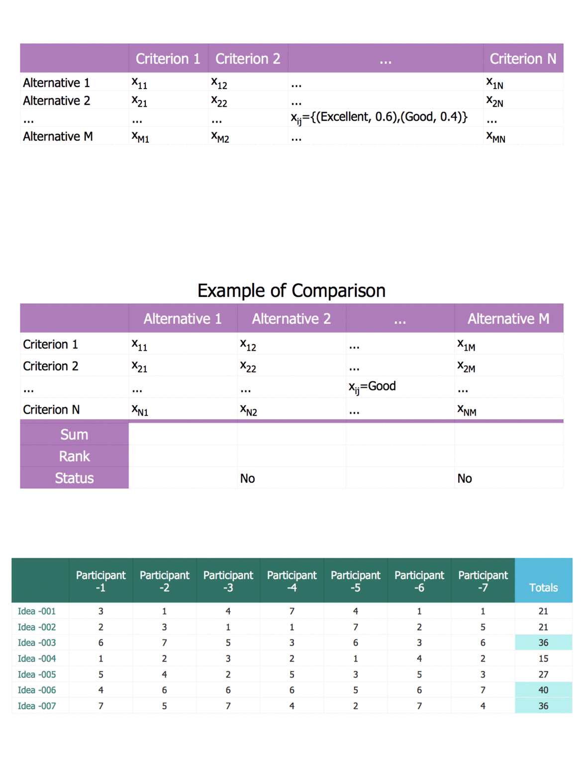
Having the pre-made vector stencils as well as the previously created examples of many drawings, including the decision matrices from the Decision Making solution may help with making the unique representation for any of the ConceptDraw DIAGRAM user. In case you doubt in being able to make the needed decision matrix professionally, then you can always use any of the already existing templates as drafts for your own drawings.- Flowchart To Find The Sum Of Given N Numbers
- Sum Of N Number Draw Flowchart
- Draw A Flowchart To Find The Sum Of N Numbers
- Flow Chart Of Sum Of N Number With Algorithm
- Draw A Flowchart To Find The Sum Of Given N Number
- Physics Symbols | Flow Chart In C To Find The Sum Of Gp Series
- Mathematical Diagrams | Flowchart And Algorithm For Sum Of G P ...
- Flow Chart Of Gp Series
- Algorithm Of Sum Of A Gp Series
- | Flow Chart Of Gp Series Program In C

