Basic Flowchart Symbols and Meaning
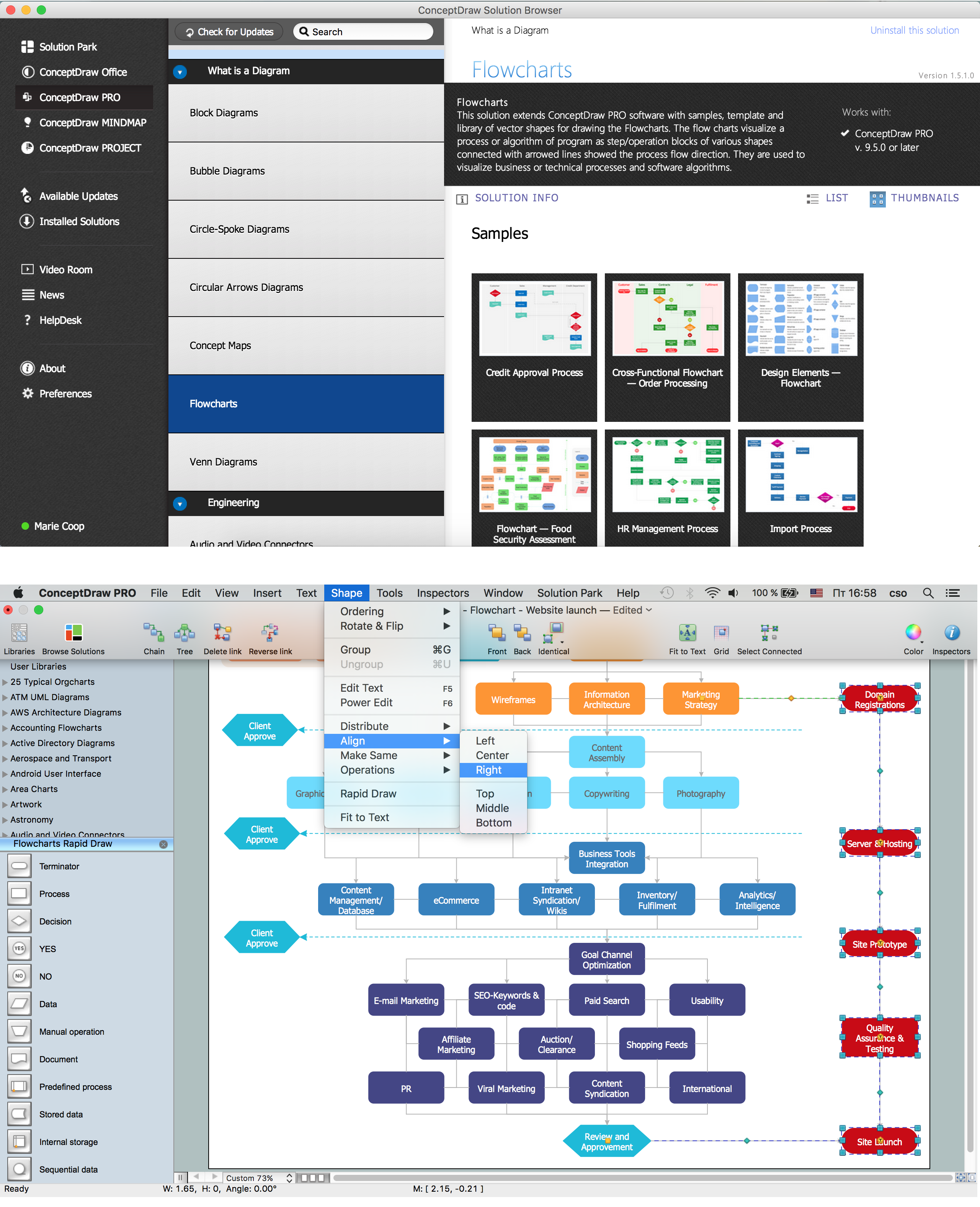
Flowcharts are the best for visually representation the business processes and the flow of a custom-order process through various departments within an organization. ConceptDraw PRO diagramming and vector drawing software extended with Flowcharts solution offers the full set of predesigned basic flowchart symbols which are gathered at two libraries: Flowchart and Flowcharts Rapid Draw. Among them are: process, terminator, decision, data, document, display, manual loop, and many other specific symbols. The meaning for each symbol offered by ConceptDraw gives the presentation about their proposed use in professional Flowcharts for business and technical processes, software algorithms, well-developed structures of web sites, Workflow diagrams, Process flow diagram and correlation in developing on-line instructional projects or business process system. Use of ready flow chart symbols in diagrams is incredibly useful - you need simply drag desired from the libraries to your document and arrange them in required order. There are a few serious alternatives to Visio for Mac, one of them is ConceptDraw PRO. It is one of the main contender with the most similar features and capabilities.
Technical Flow Chart
Flow chart is a diagrammatic representation of an algorithm and essential part of planning the system. Flow charts are widely used in technical analysis and programming for easy writing programs and explaining them to others. So, one of the most popular type of flow charts is Technical Flow Chart. Technical Flow Chart can be drawn by pencil on the paper, but it will be easier to use for designing a special software. ConceptDraw PRO diagramming and vector drawing software extended with Flowcharts Solution from the "Diagrams" Area of ConceptDraw Solution Park will be useful for this goal.Databases Access Objects Model with ConceptDraw PRO
ConceptDraw Basic gives the opportunity of interaction with any ODBC-compatible databases. For this the Database Access Objects Model is provided. All calls to the database are made by certain methods of objects of this model.Symboles Organigramme
Les organigrammes sont parfaits pour représenter visuellement des processus operationnels. Par exemple, si vous avez besoin d'afficher le flux d'un processus d'ordre personnalisé par l'entremise de divers opérateurs au sein de votre organisation, vous pouvez utiliser un organigramme. Voir aussi d'autres symboles organigramme: Symboles ordinogramme standard, symboles du flux de travail, Vérification Les symboles du schéma fonctionnel, sOrganigramme comptables des symboles, Organigramme de vente des symboles, Symboles pour organigramme des RH, Carte des symboles de processus, Diagramme de processus opérationnels, Symboles utilisés dans le schéma IDEF0.- True False Of Flow Chart Lists All Steps In Action In Right Order
- Internet Is The Example Of Connectivity True Or False
- This Statement Is True Or False Internet Is An Example Of Man
- Fault Tree Analysis Diagrams
- Design elements - Analog and digital logic | Engineering | Media ...
- Design elements - Analog and digital logic | Analog and digital logic ...
- Electrical Symbols, Electrical Diagram Symbols | Electrical Drawing ...
- Design elements - Analog and digital logic | Electrical Symbols ...
- Electrical Drawing Software | Electrical Schematic Symbols ...
- Electrical Drawing Software and Electrical Symbols | Electrical ...
- Design elements - Analog and digital logic | External digital devices ...
- 2-bit ALU - Logic gate diagram | Electrical Symbols — Analog and ...
- Design elements - Logic gate diagram
- How To use House Electrical Plan Software | Electrical Symbols ...
- Circuits and Logic Diagram Software | Electrical Drawing Software ...
- Digital Communications Network. Computer and Network Examples ...
- Design elements - Switches
- Design elements - Logic gate diagram
- Design elements - Composite assemblies | Electrical Drawing ...
- How To use House Electrical Plan Software | Design elements ...


