Mechanical Drawing Symbols

Technical Drawing Software

Interior Design. Machines and Equipment — Design Elements

Electrical Symbols — Switches and Relays

Network Security Devices

The vector stencils library "Bearings" contains 59 symbols of ball bearings, roller bearings, shafts, springs, gears, hooks, spindles, and keys.
Use it to design engineering drawings of machine tools and mechanical devices in the ConceptDraw PRO diagramming and vector drawing software extended with the Mechanical Engineering solution from the Engineering area of ConceptDraw Solution Park.
www.conceptdraw.com/ solution-park/ engineering-mechanical
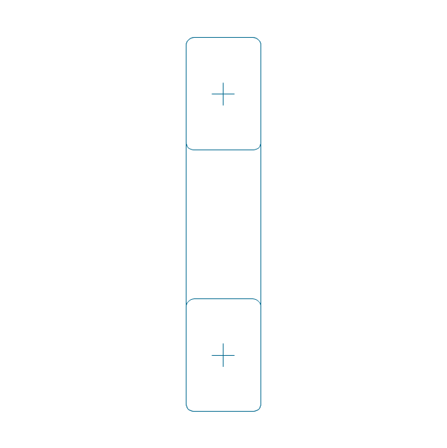
Through hole
Threaded hole 3
Threaded hole 4
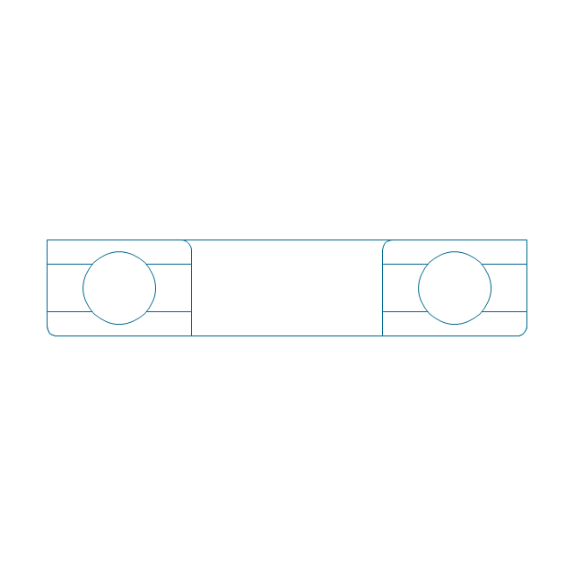
Rolling bearings 2
Rolling bearings
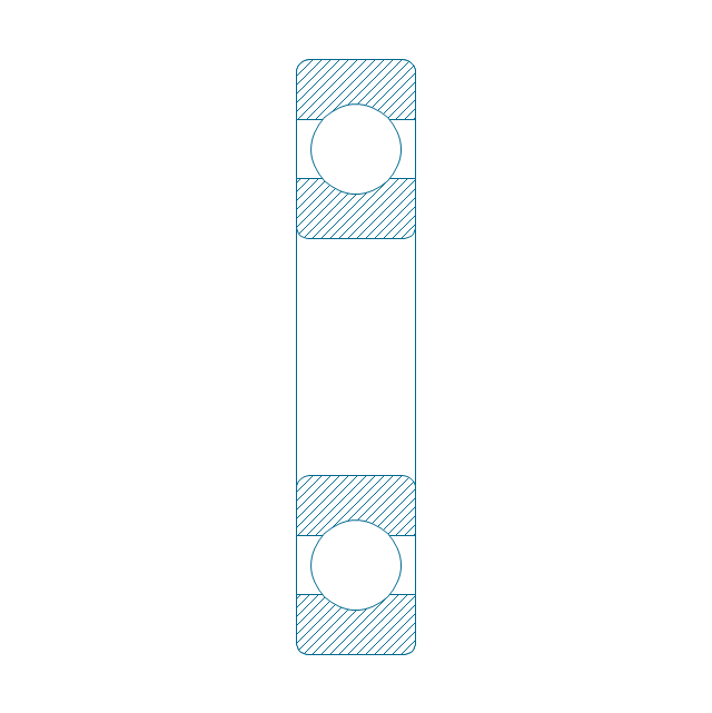
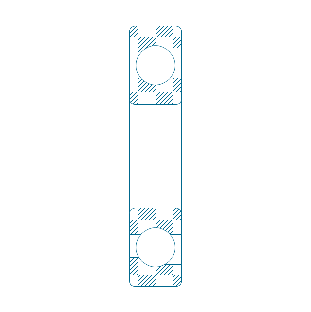
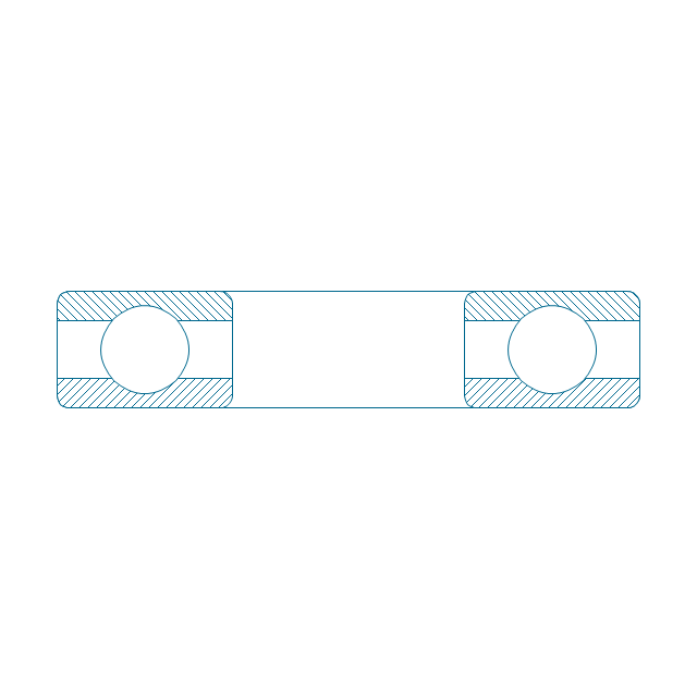
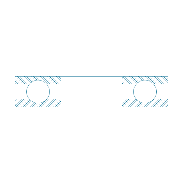
Deep groove ball bearing, hatched
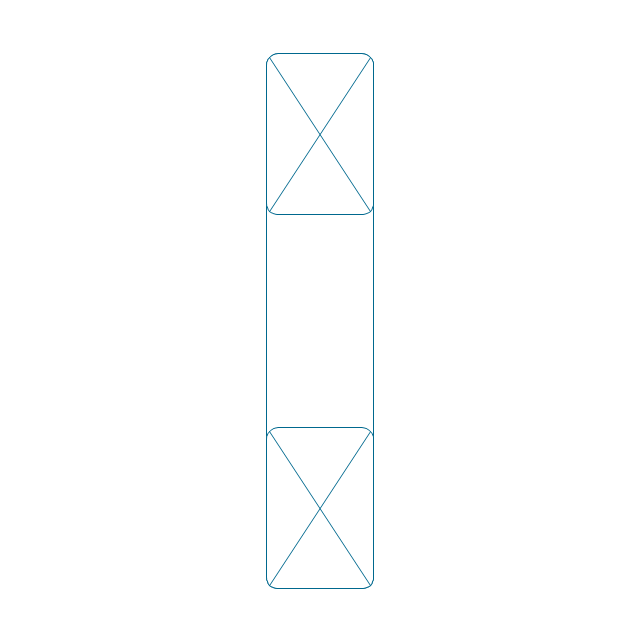
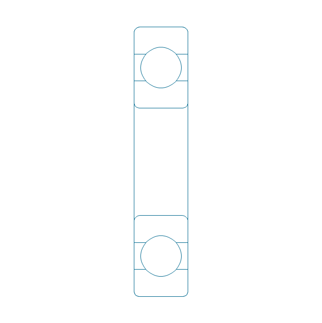
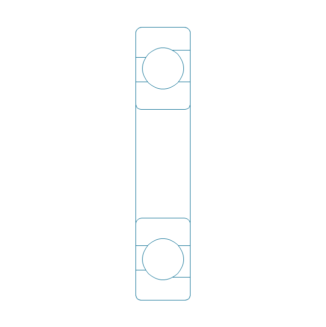
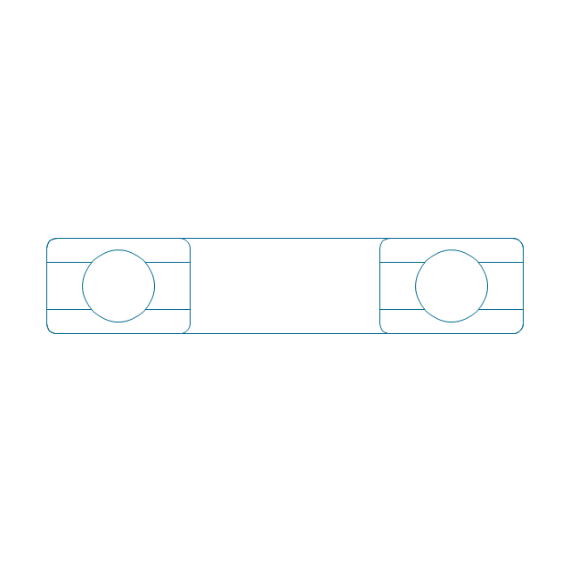
Deep groove ball bearing, unhatched
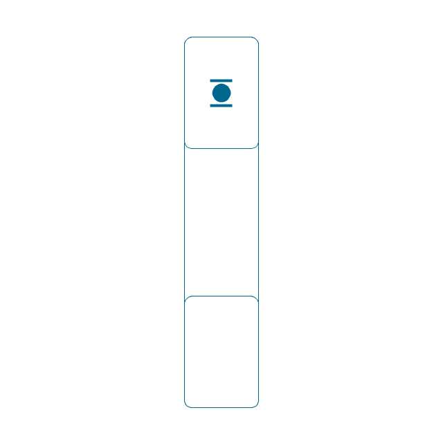
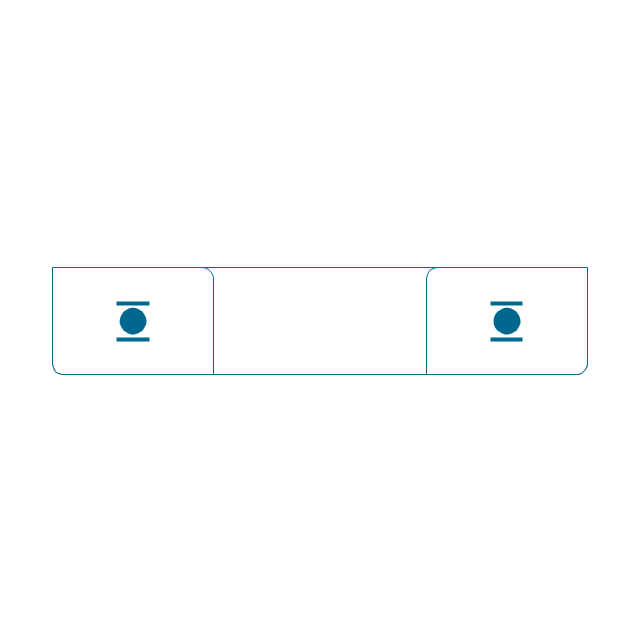
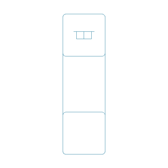
Deep groove ball bearing, simpl.
Angular contact ball bearing, simpl.
Angular contact ball bearing, unhatched
Angular contact ball bearing, hatched
Angular contact ball bearing dbl, unhatched
Angular contact ball bearing dbl, hatched
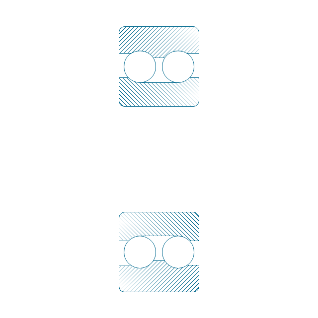
Self align. dbl ball bearing, hatched
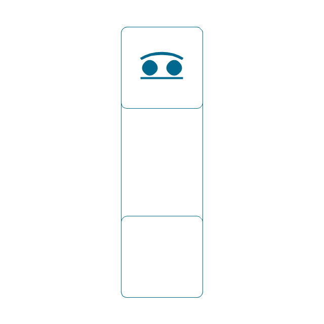
Self align. dbl bearing, simpl.
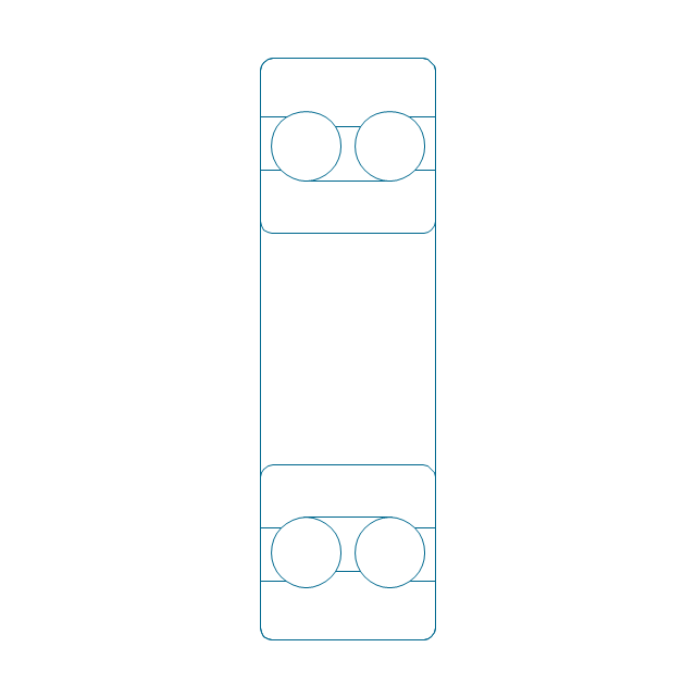
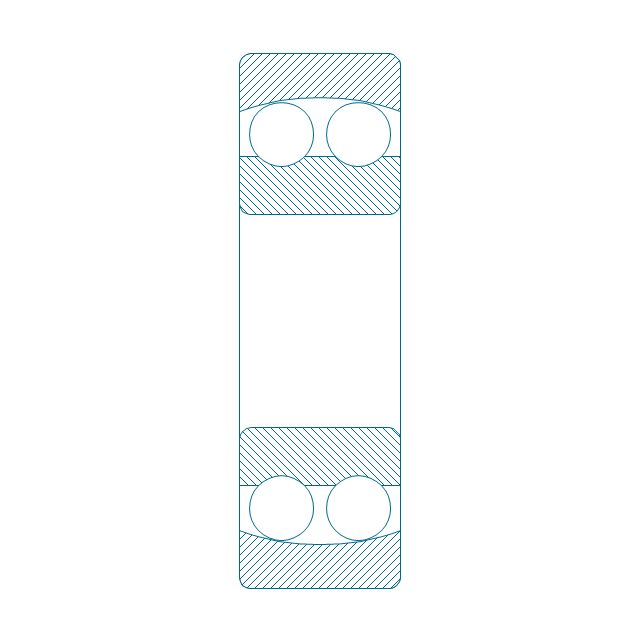
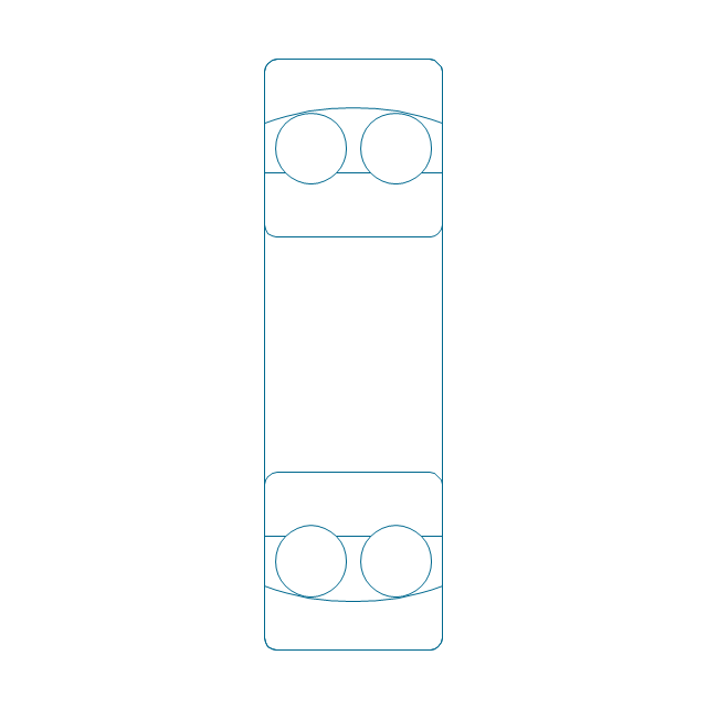
Self align. dbl ball bearing, unhatched
Thrust ball bearing, hatched
Thrust ball bearing, unhatched
Thrust ball bearing, simpl.
Thrust ball bearing, hatched 2
Thrust ball bearing, unhatched 2
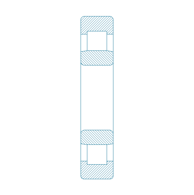
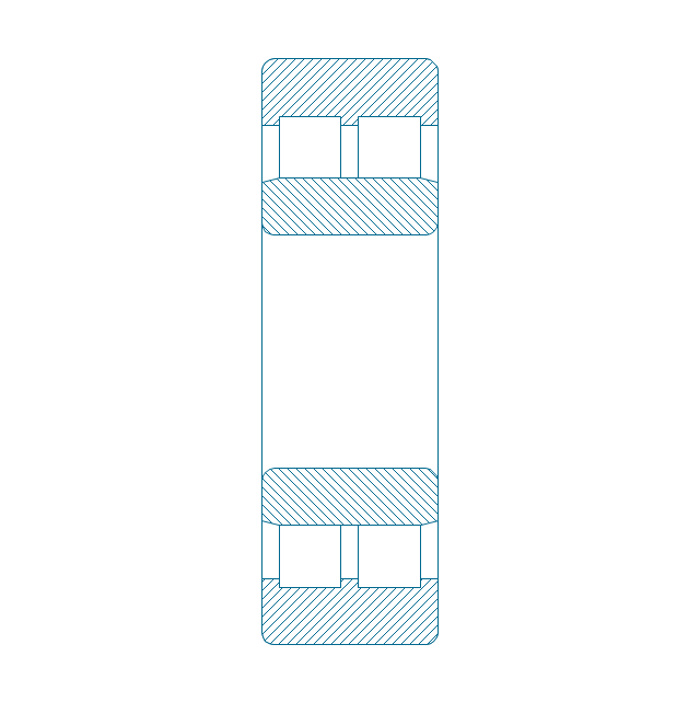
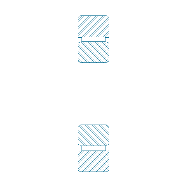
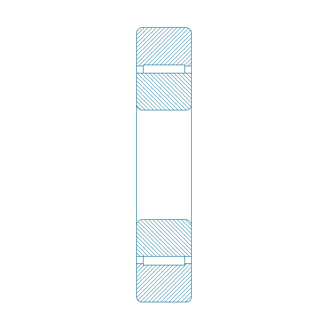
Cylindrical roller bearing, hatched
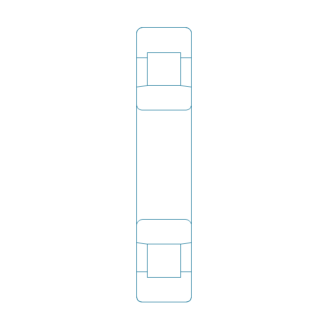
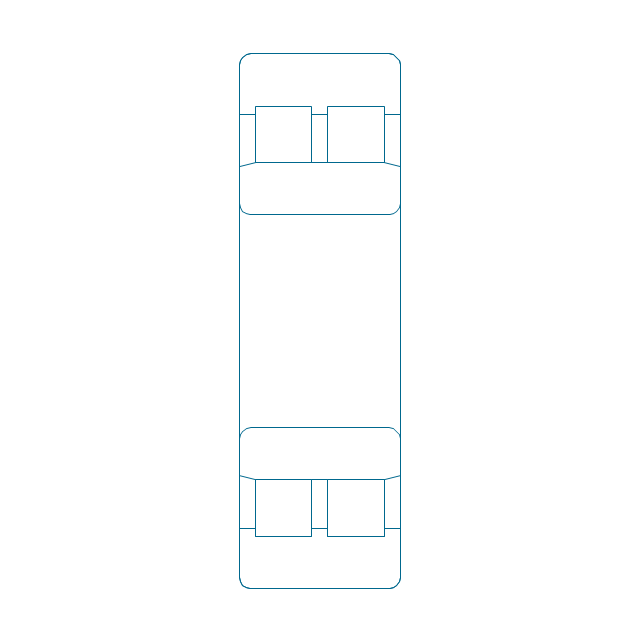
Cylindrical roller bearing, unhatched
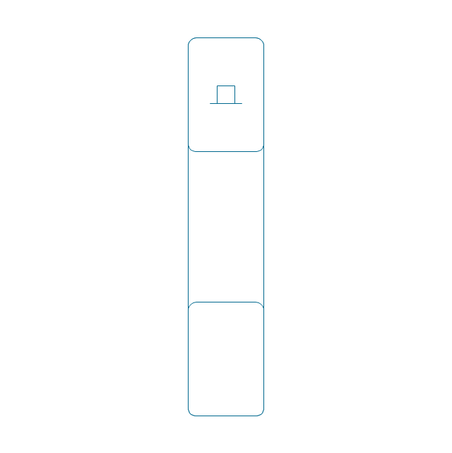
Cylindrical roller bearing, simpl.
Cylindrical roller bearing dbl, simpl.
Cylindrical roller bearing dbl, unhatched
Cylindrical roller bearing dbl, hatched
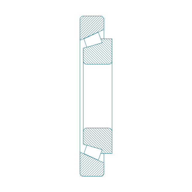
Taper roller bearing, hatched
Taper roller bearing, unhatched
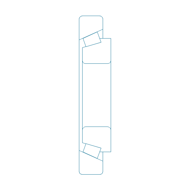
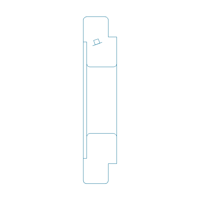
Taper roller bearing, simpl.
Needle roller bearing, hatched
Needle roller bearing, hatched 2
Needle roller bearing, unhatched
Needle roller bearing, unhatched 2
Needle roller bearing, simpl.
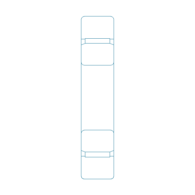
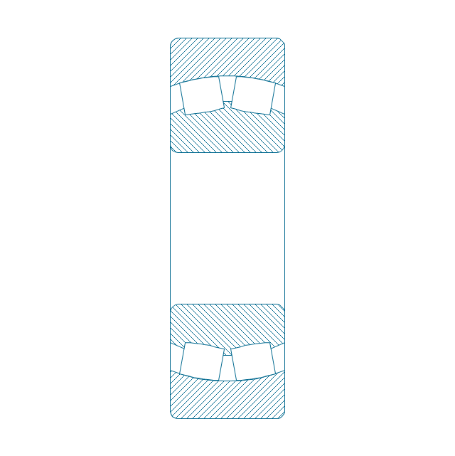
Spher. roller bearing dbl, hatched 2
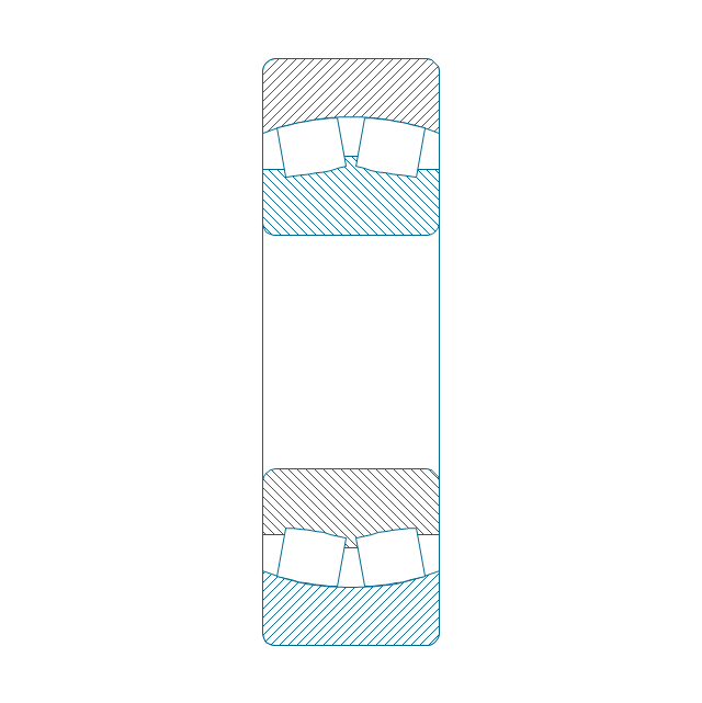
Spher. roller bearing dbl, hatched
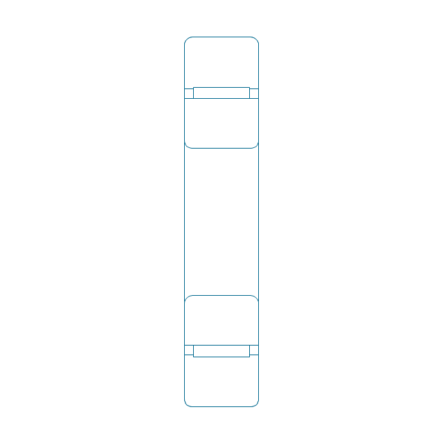
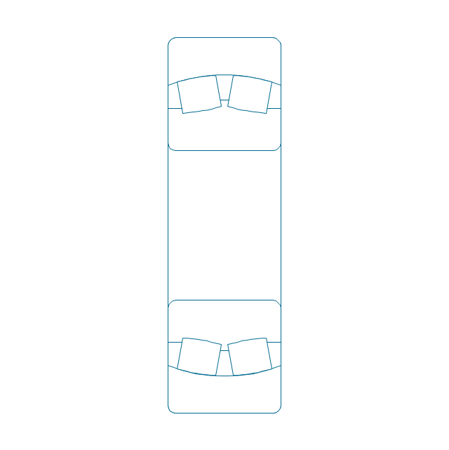
Spher. roller bearing dbl, unhatched
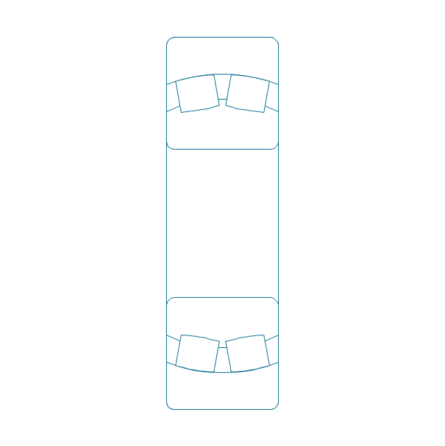
Spher. roller bearing dbl, unhatched 2
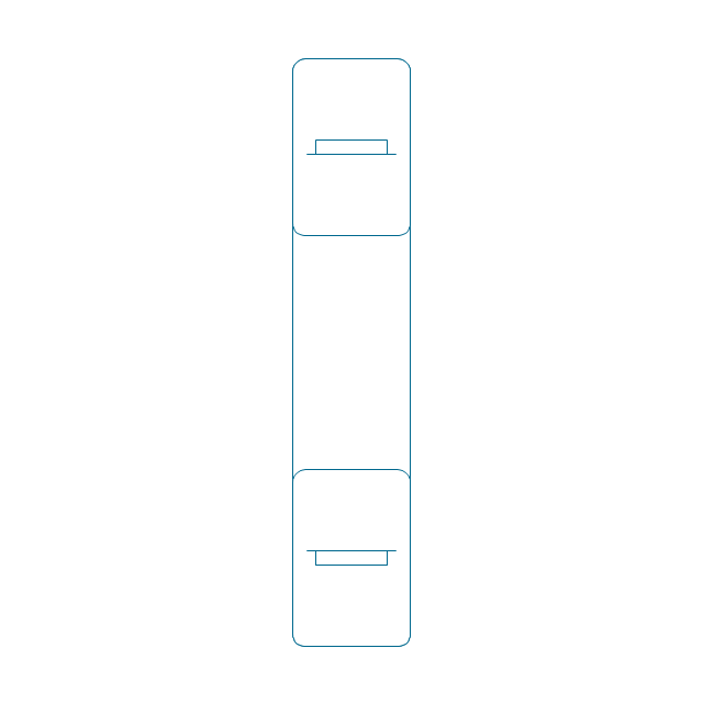
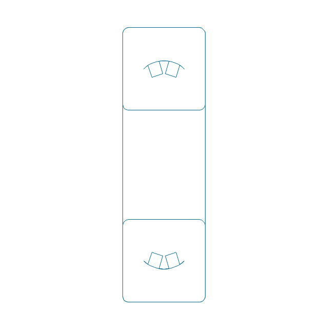
Spher. roller bearing dbl, simpl.
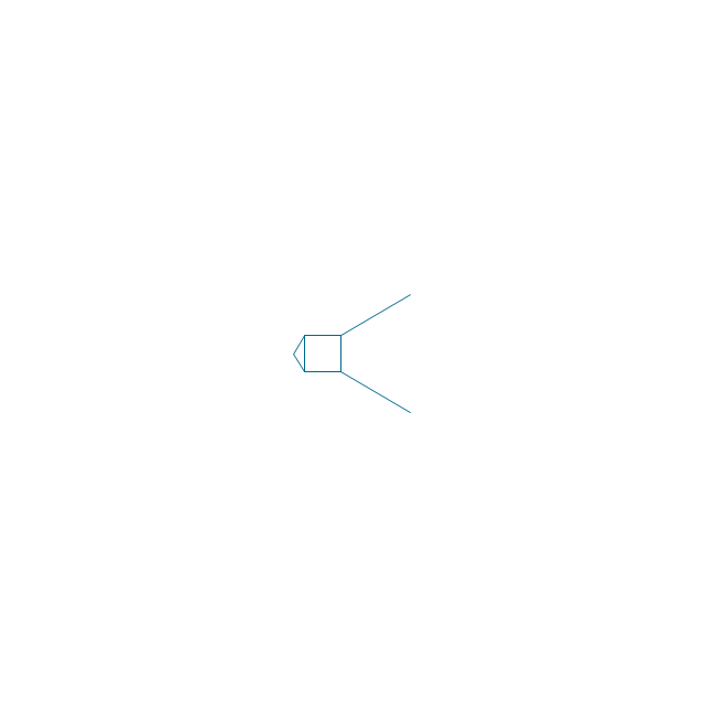
Gear
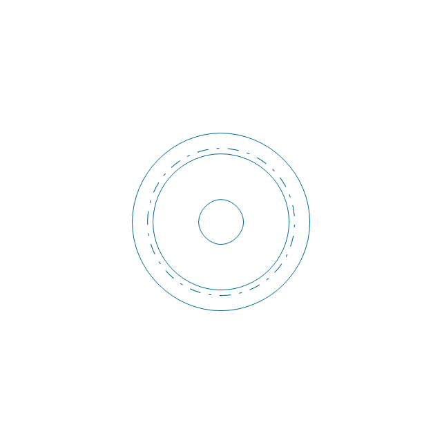
Gear (web)
-bearings---vector-stencils-library.png--diagram-flowchart-example.png)
Gear (keyway)
-bearings---vector-stencils-library.png--diagram-flowchart-example.png)
Gear (web, keyway)
-bearings---vector-stencils-library.png--diagram-flowchart-example.png)
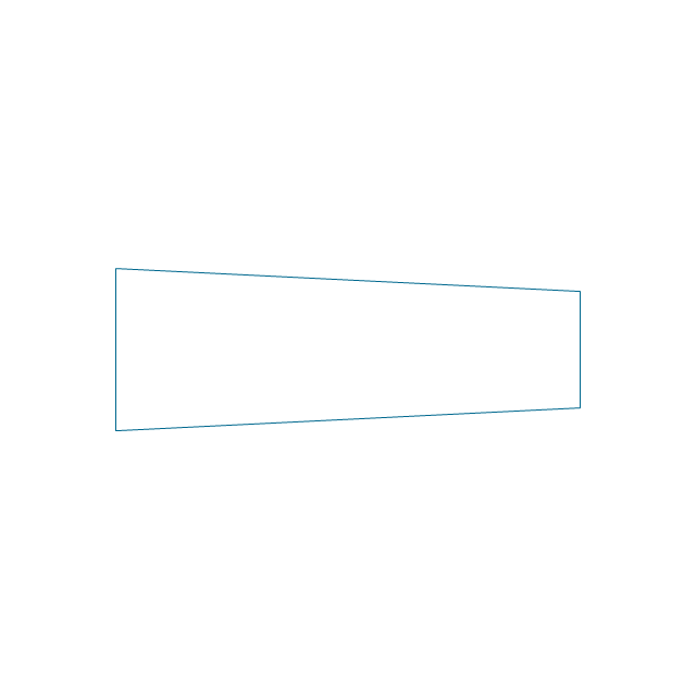
Tapered shaft
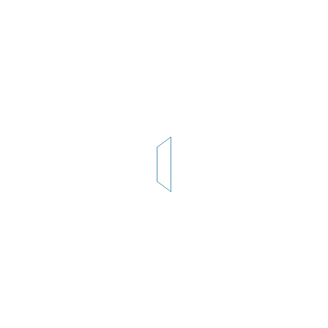
Tapered key

Tapered key (gib head)
-bearings---vector-stencils-library.png--diagram-flowchart-example.png)
Tapered shaft

Hole chamfer
Shaft chamfer

Undercut
Centering bore
Cutaway

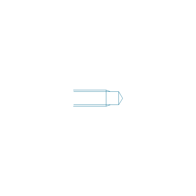
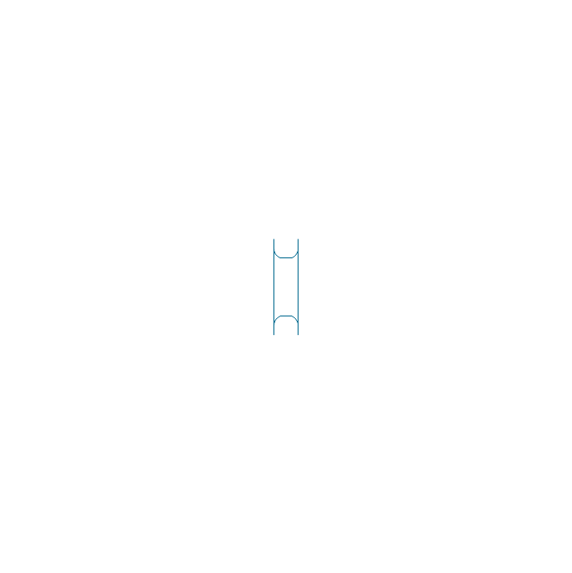
Spindle end
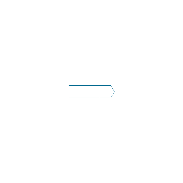
Spindle end (bore)
-bearings---vector-stencils-library.png--diagram-flowchart-example.png)
Countersunk hole

Countersunk hole 2

Threaded hole

Threaded hole 2

Example of DFD for Online Store (Data Flow Diagram)


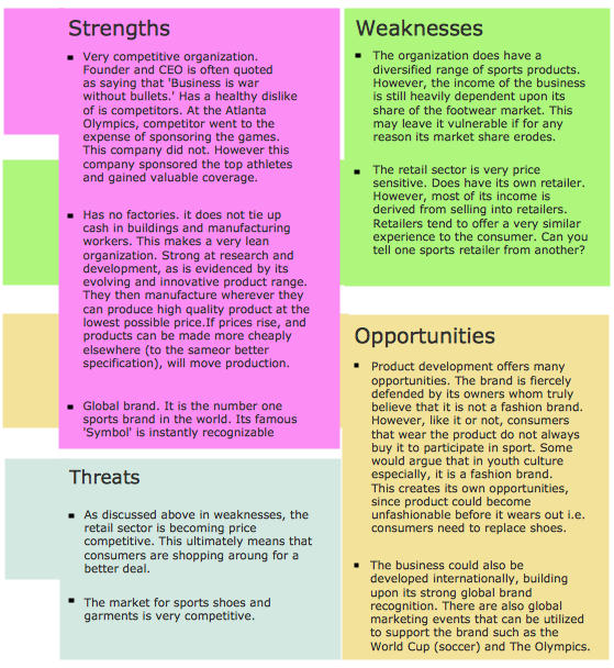
SWOT Analysis
How Do Fishbone Diagrams Solve Manufacturing Problems

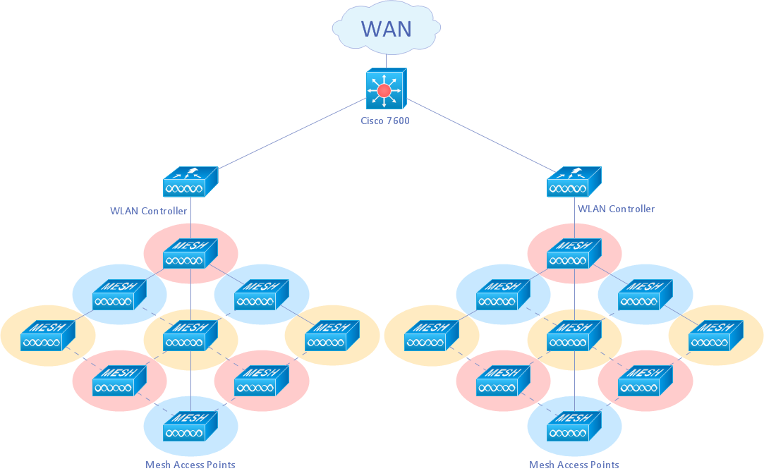
Wireless Network Drawing
- Mechanical Engineering Gears Drawings
- Symbol For Gear Mechanical Engineering Drawing
- Engineering Drawing Representation Of Gear On A Shaft
- Mechanical Drawing Symbols | Design elements - Bearings ...
- Engineering Drawing Shaft With Key And Gear
- Mechanical Drawing Symbols | Flow Diagram To Make Gear In The ...
- Mechanical Engineering | External Gear Motor Symbol
- Design elements - Bearings | Mechanical Engineering | Bearings ...
- Technic To Drawing Gear Engginering Drawing
- Symbol Of Motor Drive Gear Pump