HelpDesk
How to Create a CCTV Diagram in ConceptDraw PRO
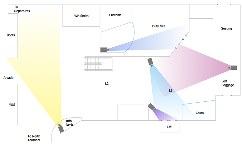
CCTV (Closed circuit television) diagram is used to depict a system of video monitoring. The CCTV diagram provides video cameras placement strategy. CCTV diagram should include the scheme of strategic placement of video cameras, which capture and transmit videos to either a private network of monitors for real-time viewing, or to a video recorder for later reference. CCTV is commonly used for surveillance and security purposes. Using ConceptDraw PRO with the Security and Access Plans Solution lets you create professional looking video surveillance CCTV system plans, security plans, and access schemes.
 ConceptDraw Solution Park
ConceptDraw Solution Park collects graphic extensions, examples and learning materials
The vector stencils library "Analog and digital logic" contains 40 element symbols of logic (threshold) gates, bistable current switches, current controllers, regulators, electrical generators, and amplifiers.
Use it for drawing the digital and analog functions in electronic circuit diagrams and electrical schematics.
"Analogue electronics (or analog in American English) are electronic systems with a continuously variable signal, in contrast to digital electronics where signals usually take only two different levels. The term "analogue" describes the proportional relationship between a signal and a voltage or current that represents the signal." [Analogue electronics. Wikipedia]
"Digital electronics, or digital (electronic) circuits, represent signals by discrete bands of analog levels, rather than by a continuous range. All levels within a band represent the same signal state. Relatively small changes to the analog signal levels due to manufacturing tolerance, signal attenuation or parasitic noise do not leave the discrete envelope, and as a result are ignored by signal state sensing circuitry.
In most cases the number of these states is two, and they are represented by two voltage bands: one near a reference value (typically termed as "ground" or zero volts) and a value near the supply voltage, corresponding to the "false" ("0") and "true" ("1") values of the Boolean domain respectively.
Digital techniques are useful because it is easier to get an electronic device to switch into one of a number of known states than to accurately reproduce a continuous range of values.
Digital electronic circuits are usually made from large assemblies of logic gates, simple electronic representations of Boolean logic functions." [Digital electronics. Wikipedia]
The example "Design elements - Analog and digital logic" was drawn using the ConceptDraw PRO diagramming and vector drawing software extended with the Electrical Engineering solution from the Engineering area of ConceptDraw Solution Park.
- Infographic Generator | Basic Diagramming | Map Infographic ...
- Block Diagram Generator Online
- Polar Graph | ConceptDraw Solution Park | Pyramid Diagram ...
- Block Diagram Generator
- Er Diagram Of Barcode Scanner And Generator
- How to Create a Fault Tree Analysis Diagram (FTD) in ConceptDraw ...
- Design elements - Stations | Electrical Diagram Symbols | Electrical ...
- Diagram Of Bio Generator Found In A Biological Laboratory
- Negative Logic Gate Circuit Diagrams
- Simple Graph Generator
- Diagram Of Generator
- Linguistics Tree Diagram Generator
- How To use House Electrical Plan Software | Electrical Drawing ...
- Signal Generator Symbol
- Free Bar Graph Generator
- Graph Scale Generator
- Maths Graph Generator
- Easy Graph Generator
- Mechanical Symbol Of Generator
- Venn Diagram Generator

