HelpDesk
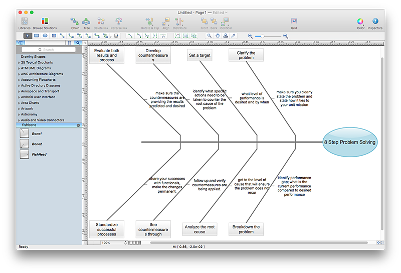
How to Create a Fishbone (Ishikawa) Diagram Quickly
A Fishbone (Ishikawa) diagram is also called cause-and-effect diagram. Fishbone diagram is often used in business to determine the cause of some problem. The diagram illustrates the main causes and sub-causes leading to an event. The main goal of the Fishbone diagram is to illustrate in a graphical way the relationship between a given outcome and all the factors that influence this outcome. The complete diagram resembles a fish skeleton as its name implies. The ability to create a Fishbone Diagram is supported by the Fishbone Diagram solution. Use ConceptDraw MINDMAP for structuring data and then ConceptDraw PRO for generating a Fishbone Diagram from mind map structure.
 Rapid UML
Rapid UML solution extends ConceptDraw PRO software with templates, samples and libraries of vector stencils for quick drawing the UML diagrams using Rapid Draw technology.
 Flowcharts
The Flowcharts Solution for ConceptDraw PRO v10 is a comprehensive set of examples and samples in several different color themes for professionals that need to graphically represent a process. Solution value is added by basic flow chart template and shapes' library of Flowchart notation. ConceptDraw PRO flow chart creator lets one depict a processes of any complexity and length, as well design of the flowchart either vertically or horizontally.
 Specification and Description Language (SDL)
For people in the field of systems engineering or system design, working with specification and description language (sdl) and finite state machines (fsm).
 Workflow Diagrams
Workflow Diagrams solution extends ConceptDraw PRO software with samples, templates and vector stencils library for drawing the work process flowcharts.
 Office Layout Plans
Office layouts and office plans are a special category of building plans and are often an obligatory requirement for precise and correct construction, design and exploitation office premises and business buildings. Designers and architects strive to make office plans and office floor plans simple and accurate, but at the same time unique, elegant, creative, and even extraordinary to easily increase the effectiveness of the work while attracting a large number of clients.
- The Graph That Illustrates The Composition And Interaction ...
- Competitor Analysis | UML Notation | Graphically Illustrate ...
- Graphically Illustrate The Composition And Interaction Between The ...
- Draw A Diagram That Illustrates The Composition Of The
- Graphically Illustrate Business Environment
- The Composition Of The Management Environment Graph
- The Composition Of The Management Environment Diagrams
- Chart Of Management Information System With Diagram
- 4 Level pyramid model diagram - Information systems types ...
- Percentage Pie Chart. Pie Chart Examples | Atmosphere air ...
- Fishbone Diagrams | SWOT Analysis Software | Fishbone Diagram ...
- Organizational Charts with ConceptDraw PRO | Orgchart ...
- Construct A Data Flow Diagram For University Management System
- Example of Organizational Chart | ConceptDraw PRO ...
- A process with normal flow | Marketing diagrams - Vector stencils ...
- Process Flowchart | Energy resources diagram | Draw Fishbone ...
- How Is A Timeline Graph Applied To Problem Solving
- Venn Diagram Examples for Problem Solving. Environmental Social ...
- Graphical Reprasentation Of Levels Of Management
