Electrical Symbols, Electrical Diagram Symbols
When drawing Electrical Schematics, Electrical Circuit Diagrams, Power Systems Diagrams, Circuit and Wiring Diagrams, Digital and Analog Logic Schemes, you will obligatory need the electrical symbols and pictograms to represent various electrical and electronic devices, such as resistors, wires, transistors, inductors, batteries, switches, lamps, readouts, amplifiers, repeaters, relays, transmission paths, semiconductors, generators, and many more. Today these symbols are internationally standardized, so the diagrams designed using them are recognizable and comprehensible by specialists from different countries. Electrical Engineering Solution included to ConceptDraw Solution Park provides 26 libraries with 926 commonly used electrical schematic and electrical engineering symbols making the reality the easy drawing of Electrical diagrams, schematics and blueprints. Now you need only a few minutes to create great-looking Electrical diagram, simply choose required electrical design elements from the libraries, drag them on the needed places at the document and connect in a suitable way.Interior Design. Office Layout Plan Design Element
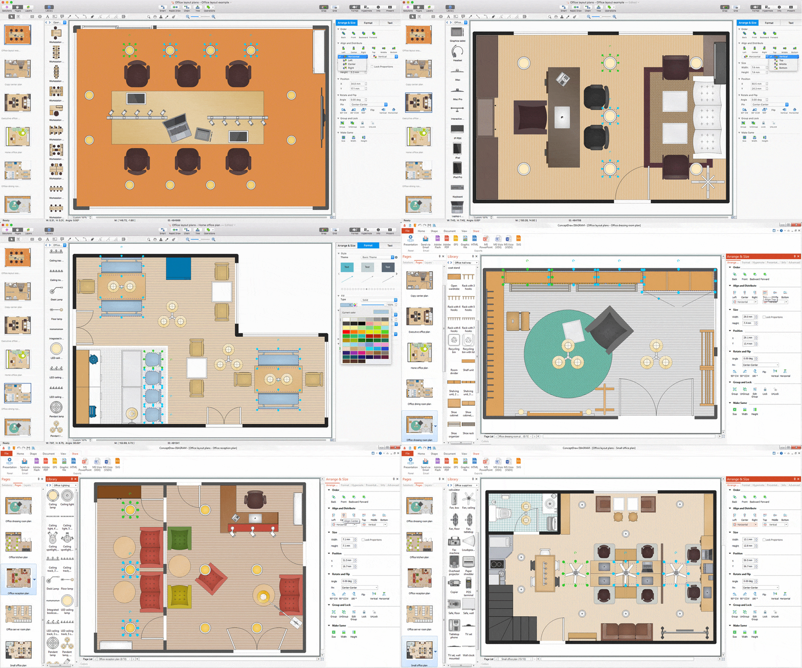
Lucky interior design is an integral part of succesful work at office. The important challenge in office design planning is to find a balance between two main office activities: concentration and communication. Primarily you need to determine with a type of office space, this can be an open space or separate rooms. The first type is more suitable for communication and rapid interaction. That's why open offices and combined spaces are modern types of work space and often used, especially for private offices. Traditional office basically represents separate rooms arranged along the corridor. It is applied for the companies with small number of people or for enterprises divided on separate departments, and is practically inapplicable for teamwork. ConceptDraw DIAGRAM diagramming and vector drawing software extended with Office Layout Plans solution offers a lot of vector stencils libraries with design elements of office furniture and equipment for effective office interior design and office space planning, for easy creation Office Floor Plans and Office Layout Plans. Use ConceptDraw DIAGRAM to visualize process flowcharts, network architecture and program workflows like Visio for Mac and even more. The software can be used with different fields like business, engineering and construction, etc.
UML Class Diagram Notation
When it comes to system construction, a class diagram is the most widely used diagram. UML Class Diagrams is a type of static structure diagram that is used for general conceptual modeling of the systematics of the application. Such a diagram would illustrate the object-oriented view of a system. The object orientation of a system is indicated by a class diagram. It describes the structure of a system by showing the general issues,classes of a system, attributes, operations, interfaces, inheritance, and the relationships between them.- Electrical Drawing Software | Interior Design Office Layout Plan ...
- Design elements - Rotating equipment | Electrical and telecom ...
- Design elements - Chemical engineering | Design elements ...
- Electrical Equipment Symbols
- Company Drawing Mechanical Using Symbols
- Engineering | ConceptDraw PRO | Technical drawing - Machine ...
- UML Notation | Design elements - Bearings | UML Class Diagram ...
- Design elements - Internet symbols
- GUI Prototyping with ConceptDraw PRO | iPhone OS (iOS) graphic ...
- Engineering | Technical drawing - Machine parts assembling ...
- Natural Gas Symbol
- iPhone OS (iOS) graphic user interface (GUI) - Activity indicator view ...
- Basic Flowchart Symbols and Meaning | Flowchart design ...
- GUI Software | Mac OS GUI Software | Graphic User Interface ...
- Exchange Mind Map with Evernote | iPhone OS (iOS) graphic user ...
- Technical drawing - Machine parts assembling | Engineering ...
- Bearing Symbol
- Electrical Diagram Symbols
- Design elements - Power sources | Power sources - Vector stencils ...
- Flow Chart Diagram Examples | Create a Flow Chart | Example of ...


