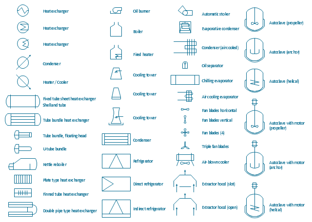
The vector stencils library "Heating equipment" contains 42 symbols of regenerators, intercoolers, heaters, and condensers.
Use these shapes for drawing cooling systems, heat recovery systems, thermal, heat transfer and mechanical design, and process flow diagrams (PFD).
"Heating or cooling of processes, equipment, or enclosed environments are within the purview of thermal engineering.
One or more of the following disciplines may be involved in solving a particular thermal engineering problem:
Thermodynamics,
Fluid mechanics,
Heat transfer,
Mass transfer.
Thermal engineering may be practiced by mechanical engineers and chemical engineers.
One branch of knowledge used frequently in thermal engineering is that of thermofluids." [Thermal engineering. Wikipedia]
The design elements example "Heating equipment" was created using the ConceptDraw PRO diagramming and vector drawing software extended with the Chemical and Process Engineering solution from the Engineering area of ConceptDraw Solution Park.
The vector stencils library "Heating equipment" contains 42 symbols of regenerators, intercoolers, heaters, and condensers.
Use these shapes for drawing cooling systems, heat recovery systems, thermal, heat transfer and mechanical design, and process flow diagrams (PFD) in the ConceptDraw PRO software extended with the Chemical and Process Engineering solution from the Chemical and Process Engineering area of ConceptDraw Solution Park.
www.conceptdraw.com/ solution-park/ engineering-chemical-process
- Process Flow Diagram Symbols | Crude oil distillation unit - PFD ...
- Fired Heater Symbol
- Diagram Of A Line Heater In A Gas Plant
- Crude oil distillation unit - PFD | Process Flow Diagram Symbols ...
- Natural gas condensate - PFD | Jet fuel mercaptan oxidation treating ...
- Amine treating unit schematic diagram | Heating equipment - Vector ...
- Crude oil distillation unit - PFD | Process flow diagram - Typical oil ...
- Process flow diagram - Typical oil refinery | Crude oil distillation unit ...
- Crude oil distillation unit - PFD | Chemical and Process Engineering ...
- Crude oil distillation unit - PFD | Jet fuel mercaptan oxidation treating ...
- Kettle Process Flow Diagram
- Natural gas condensate - PFD | EU greenhouse gas emissions ...
- Crude oil distillation unit - PFD | Water Heat Exchanger In Gas Plant
- Lpg Plant Pfd
- Crude oil distillation unit - PFD | Process flow diagram - Typical oil ...
- Process Flow Diagram Symbols | Process Engineering | Process ...
- Crude oil distillation unit - PFD | Process flow diagram - Typical oil ...
- Process Flowchart | Chemical and Process Engineering | Process ...
- Process Flowchart | Process Flow Diagram Symbols | Process ...
- Process flow diagram - Typical oil refinery | Crude oil distillation unit ...













-heating-equipment---vector-stencils-library.png--diagram-flowchart-example.png)


-heating-equipment---vector-stencils-library.png--diagram-flowchart-example.png)
-heating-equipment---vector-stencils-library.png--diagram-flowchart-example.png)
-heating-equipment---vector-stencils-library.png--diagram-flowchart-example.png)
-heating-equipment---vector-stencils-library.png--diagram-flowchart-example.png)
-heating-equipment---vector-stencils-library.png--diagram-flowchart-example.png)
-heating-equipment---vector-stencils-library.png--diagram-flowchart-example.png)
-heating-equipment---vector-stencils-library.png--diagram-flowchart-example.png)
-heating-equipment---vector-stencils-library.png--diagram-flowchart-example.png)


-heating-equipment---vector-stencils-library.png--diagram-flowchart-example.png)


