Mechanical Drawing Symbols

 Mechanical Engineering
This solution extends ConceptDraw DIAGRAM.9 mechanical drawing software (or later) with samples of mechanical drawing symbols, templates and libraries of design elements, for help when drafting mechanical engineering drawings, or parts, assembly, pneumatic,
This technical drawing shows the machine parts assembly using joining by threaded fasteners.
"Assembling (joining of the pieces) is done by welding, binding with adhesives, riveting, threaded fasteners, or even yet more bending in the form of a crimped seam. Structural steel and sheet metal are the usual starting materials for fabrication, along with the welding wire, flux, and fasteners that will join the cut pieces. As with other manufacturing processes, both human labor and automation are commonly used. The product resulting from fabrication may be called a fabrication. Shops that specialize in this type of metal work are called fab shops. The end products of other common types of metalworking, such as machining, metal stamping, forging, and casting, may be similar in shape and function, but those processes are not classified as fabrication." [Metal fabrication. Wikipedia]
This mechanical engineering drawing example was designed using ConceptDraw PRO diagramming and vector drawing software extended with Mechanical Engineering solution from Engineering area of ConceptDraw Solution Park.

The vector stencils library "Welding" contains 38 welding joint symbols to identify fillets, contours, resistance seams, grooves, surfacing, and backing.
Use it to indicate welding operations on working drawings in the ConceptDraw PRO diagramming and vector drawing software extended with the Mechanical Engineering solution from the Engineering area of ConceptDraw Solution Park.
www.conceptdraw.com/ solution-park/ engineering-mechanical
Use it to indicate welding operations on working drawings in the ConceptDraw PRO diagramming and vector drawing software extended with the Mechanical Engineering solution from the Engineering area of ConceptDraw Solution Park.
www.conceptdraw.com/ solution-park/ engineering-mechanical
Additional arrow
Text block

Fillet

Slot / plug

Stud

Resistance seam

Backing

Surfacing

Flange corner

Flange edge

Square groove

V-groove

Bevel groove

U-groove

J-groove

Flare V groove

Flare bevel groove

Scarf

Melt through weld

Field weld

Backing / spacer

Insert

Arrow with bend
Arrow with bend, tail
Arrow with bend, circle
Arrow with bend, circle, tail
Arrow
Arrow, tail

Arrow, circle

Arrow, circle, tail

Spot

Projection weld

Contour, concave

Contour, convex

Contour, flush

Contour angled, concave

Contour angled, convex

Contour angled, flush

Square butt weld

Closed square butt weld

Single-bevel butt weld

Double-bevel butt weld

Single-V butt weld

Double-V butt weld

Single-J butt weld

Double-J butt weld

Single-U butt weld

Double-U butt weld

Flange butt weld

Tee butt weld

Flare butt weld

Square butt joint

Single V preparation joint

Lap joint

T-joint

Butt weld

Butt weld, single-V

Bilateral lap weld

Tee weld

Angular weld

Mechanical weld

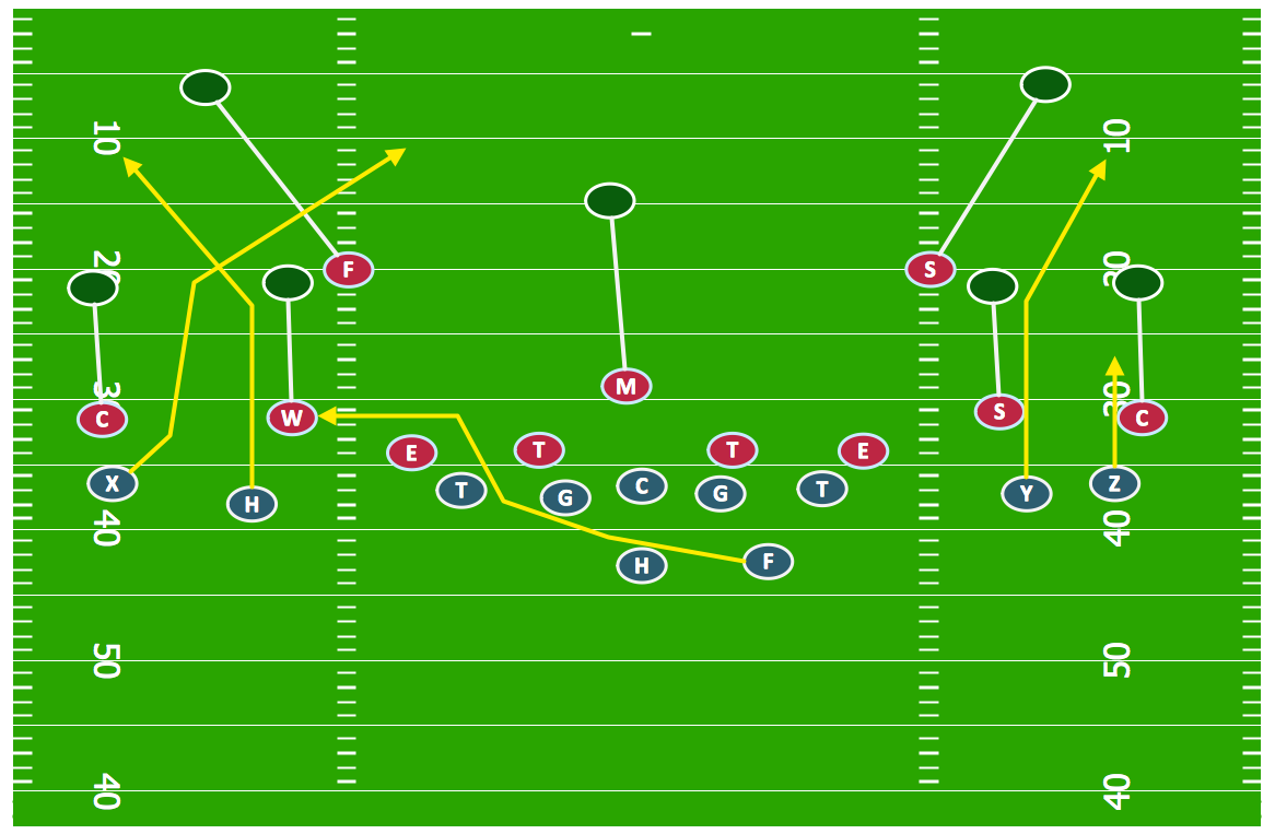
Offensive Strategy — Spread Offense Diagram
The vector stencils library "Welding" contains 38 welding joint symbols to identify fillets, contours, resistance seams, grooves, surfacing, and backing.
Use it to indicate welding operations on working drawings.
"Welding is a fabrication or sculptural process that joins materials, usually metals or thermoplastics, by causing coalescence. This is often done by melting the workpieces and adding a filler material to form a pool of molten material (the weld pool) that cools to become a strong joint, with pressure sometimes used in conjunction with heat, or by itself, to produce the weld. This is in contrast with soldering and brazing, which involve melting a lower-melting-point material between the workpieces to form a bond between them, without melting the workpieces.
Many different energy sources can be used for welding, including a gas flame, an electric arc, a laser, an electron beam, friction, and ultrasound.
Welds can be geometrically prepared in many different ways. The five basic types of weld joints are the butt joint, lap joint, corner joint, edge joint, and T-joint (a variant of this last is the cruciform joint). Other variations exist as well - for example, double-V preparation joints are characterized by the two pieces of material each tapering to a single center point at one-half their height. Single-U and double-U preparation joints are also fairly common - instead of having straight edges like the single-V and double-V preparation joints, they are curved, forming the shape of a U. Lap joints are also commonly more than two pieces thick - depending on the process used and the thickness of the material, many pieces can be welded together in a lap joint geometry." [Welding. Wikipedia]
The shapes example "Design elements - Welding" was created using the ConceptDraw PRO diagramming and vector drawing software extended with the Mechanical Engineering solution from the Engineering area of ConceptDraw Solution Park.
Welding joint symbols

Basketball Court Dimensions

The vector stencils library "Vessels" contains 40 symbols of vessels, containers, tanks, drums, and basins.
Use it for drawing industrial and manufacturing process flow diagrams, materials handling systems, and feed systems in the ConceptDraw PRO software extended with the Chemical and Process Engineering solution from the Chemical and Process Engineering area of ConceptDraw Solution Park.
www.conceptdraw.com/ solution-park/ engineering-chemical-process
Tray (dashed)
-vessels---vector-stencils-library.png--diagram-flowchart-example.png)
Tray (solid)
-vessels---vector-stencils-library.png--diagram-flowchart-example.png)
Water surface

Branch fitting

Access point

Flanged access point

Vessel flat ends

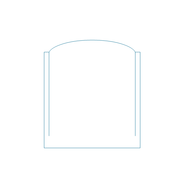
Vessel curved ends

Vessel angled ends

Column

Column (seam)
-vessels---vector-stencils-library.png--diagram-flowchart-example.png)
Tray column

Fluid contacting

Reaction vessel

Open tank with lip

Open tank

Clarifier

Closed tank

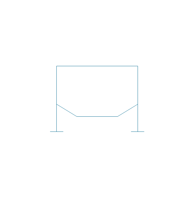
Closed tank (peaked roof)
-vessels---vector-stencils-library.png--diagram-flowchart-example.png)
Closed tank (sump)
-vessels---vector-stencils-library.png--diagram-flowchart-example.png)
Closed tank (sump, peaked roof)
-vessels---vector-stencils-library.png--diagram-flowchart-example.png)
Covered tank fixed roof

Covered tank floating roof

Covered tank fixed roof (sump)
-vessels---vector-stencils-library.png--diagram-flowchart-example.png)
Covered tank floating roof (sump)
-vessels---vector-stencils-library.png--diagram-flowchart-example.png)
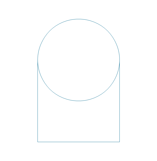
Gas holder
Storage sphere
Barrel

Gas cylinder

Bag

Carrying vessel moveable

Carrying vessel

Carrying vessel cargo
Autoclave anchor

Autoclave helical
Autoclave propeller

Autoclave anchor (motor)
-vessels---vector-stencils-library.png--diagram-flowchart-example.png)
Autoclave helical (motor)
-vessels---vector-stencils-library.png--diagram-flowchart-example.png)
Autoclave propeller (motor)
-vessels---vector-stencils-library.png--diagram-flowchart-example.png)
Tank

Basketball Court Dimensions
- Mechanical Drawing Symbols | Vessels - Vector stencils library ...
- Seam Line Diagram
- Mechanical Drawing Symbols | Welding - Vector stencils library ...
- Technical drawing - Machine parts assembling | Mechanical ...
- How to Create a Mechanical Diagram | Technical Drawing Software ...
- Basketball Court Dimensions | Mechanical Engineering | Types Of ...
- Mechanical Drawing Symbols | Ptoduction Drawing Seam Weld ...
- Seam Welding Symbol
- Mechanical Engineering | Draw Sketch Of Seam Welding
- Technical drawing - Machine parts assembling | Process Flowchart ...
- Welding - Vector stencils library | Mechanical Engineering | Sketch ...
- Technical Drawing Software | How to Create a Mechanical Diagram ...
- Mechanical Engineering | Mechanical Drawing Symbols | Welding ...
- Mechanical Engineering | Star Network Topology | Software ...
- Elements location of a welding symbol | Mechanical Engineering ...
- Mechanical Drawing Symbols | Technical drawing - Machine parts ...
- Mechanical Drawing Symbols | Technical Drawing Software | How to ...
- Mechanical Engineering | Mechanical Drawing Symbols | How to ...
- Technical drawing - Machine parts assembling | Mechanical ...