How to Draw a Landscape Design Plan
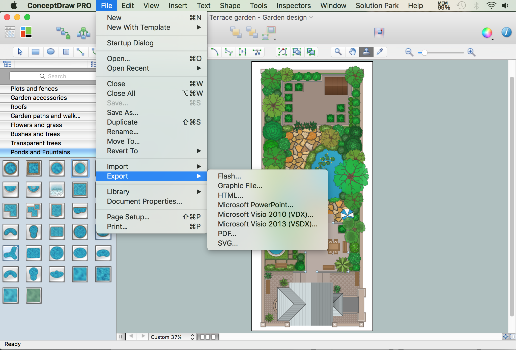
Building Drawing Software for Design Site Plan


Interior Design. Storage and Distribution — Design Elements

Building Drawing. Design Element Site Plan

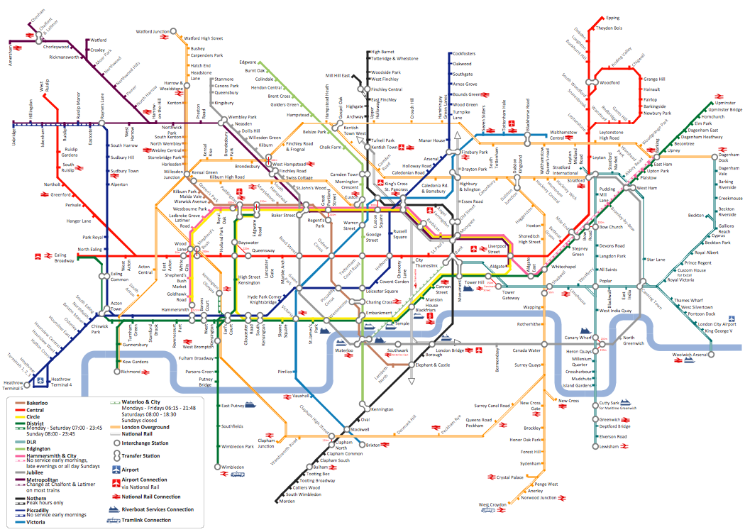
How to draw Metro Map style infographics? (London)
Cisco Products Additional. Cisco icons, shapes, stencils and symbols

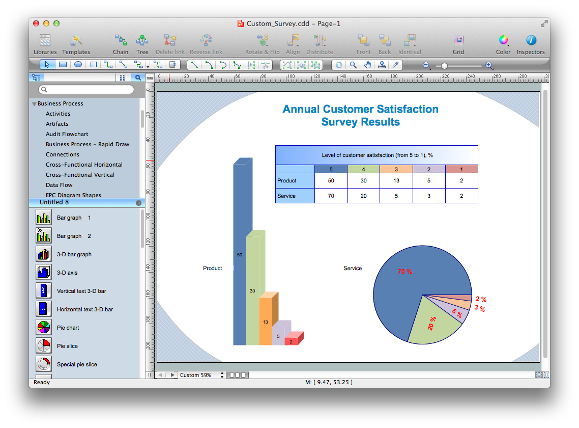
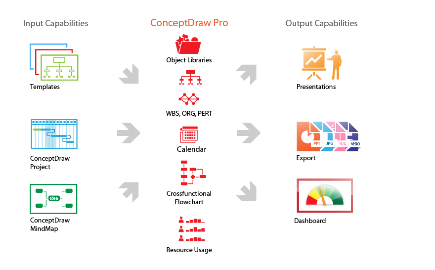
Is ConceptDraw DIAGRAM an Alternative to Microsoft Visio?
Ring Network Topology

The vector stencils library "Cisco network topology" contains 89 symbols of Cisco network devices and design elements for drawing computer network topology diagrams.
"There are two basic categories of network topologies:
(1) Physical topologies,
(2) Logical topologies.
The shape of the cabling layout used to link devices is called the physical topology of the network. This refers to the layout of cabling, the locations of nodes, and the interconnections between the nodes and the cabling. The physical topology of a network is determined by the capabilities of the network access devices and media, the level of control or fault tolerance desired, and the cost associated with cabling or telecommunications circuits.
The logical topology in contrast, is the way that the signals act on the network media, or the way that the data passes through the network from one device to the next without regard to the physical interconnection of the devices." [Network topology. Wikipedia]
The symbols example "Cisco network topology - Vector stencils library" was created using the ConceptDraw PRO diagramming and vector drawing software extended with the Cisco Network Diagrams solution from the Computer and Networks area of ConceptDraw Solution Park.
www.conceptdraw.com/ solution-park/ computer-networks-cisco
Router

Broadband router

Router firewall

Wireless router

Workgroup switch

ATM switch

ISDN switch

Multilayer switch

Protocol translator

Communications server

Transpath

Bridge

Terminal server

Route switch processor

Content engine (cache director)
-cisco-network-topology---vector-stencils-library.png--diagram-flowchart-example.png)
Management engine (ME 1100)
-cisco-network-topology---vector-stencils-library.png--diagram-flowchart-example.png)
Switch processor

ITP

Voice gateway

BBSM

ATA

SIP Proxy server

NetRanger

Cisco 1000

IP

System controller

ACE

Directory server

ADM

Cisco Unity Express

Unity server

Cisco security

CallManager

DSLAM

H.323

CDM (Content Distribution Manager)
-cisco-network-topology---vector-stencils-library.png--diagram-flowchart-example.png)
ICM

Access point

Wireless bridge

Wireless connectivity

Guard

Mobile access router

Carrier Routing System (CRS)
-cisco-network-topology---vector-stencils-library.png--diagram-flowchart-example.png)
Vault

Workstation

PC

Macintosh

Cloud, gold

Cloud, white

Cloud, standard color

Cisco security management

PBX

DPT

Government building

Headquarters, blue

Router in building

Man

Woman

Workgroup switch, subdued

Router, subdued

File server

Firewall, horizontal

Firewall, vertical

Firewall, vertical, subdued

Lock

Key

Lock and key

Car

Truck

File cabinet

Breakout box

Breakout box, blue

Host

Relational database

Modem

BBS (Bulletin Board System)
-cisco-network-topology---vector-stencils-library.png--diagram-flowchart-example.png)
Satellite

Satellite dish

UPS

RPS

MAU

PAD

PAD X.28

Diskette

Contact center

Page icon
Antenna

Antenna, blue

Radio tower

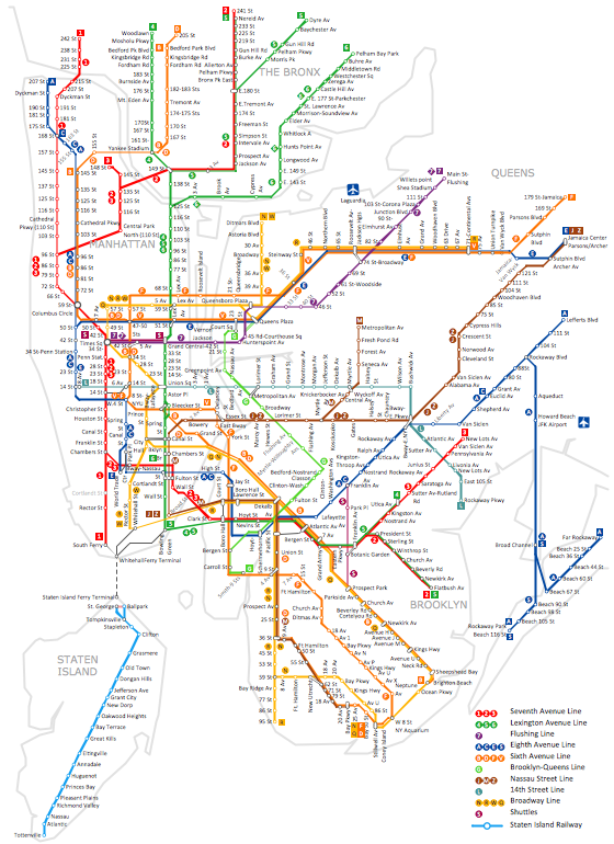
How to draw Metro Map style infographics? (New York)
Product Overview
Network Glossary Definition


- Bridge Symbols Floor Plan
- Floor Plan Symbols
- Bridges With Hub With Fire Wall Modems Draw The Layout Diagram
- Network Layout Floor Plans | Design elements - Network layout ...
- Network Layout Floor Plans | Design elements - Network layout ...
- Computer Network Diagrams | Computer and Networks Area ...
- Network Layout | Network Layout Floor Plans | Network ...
- How To Draw A Floor Plan For A Computer Centre
- Interior Design Office Layout Plan Design Element | Design ...
- Network Layout Floor Plans | Ethernet local area network layout floor ...
- Network Layout Floor Plans | Ethernet local area network layout floor ...
- Network Layout Floor Plans | Network Layout | Network Components ...
- Symbol for Pool Table for Floor Plans | Building Drawing Software ...
- Interior Design Storage and Distribution - Design Elements | Interior ...
- Diagram Showing A Repeater Bridge Switch Router Connections
- Kinds Of Wall Symbol In Floor Plan
- Design elements - Network layout floorplan | Network Diagram ...
- Design elements - Network layout floorplan | Building Drawing ...
- How To use Switches in Network Diagram
- Network Layout Floor Plans | Network Layout | Local area network ...