 Mechanical Engineering
This solution extends ConceptDraw PRO v.9 mechanical drawing software (or later) with samples of mechanical drawing symbols, templates and libraries of design elements, for help when drafting mechanical engineering drawings, or parts, assembly, pneumatic,
 Engineering
This solution extends ConceptDraw PRO v9.4 with the ability to visualize industrial systems in electronics, electrical, chemical, process, and mechanical engineering.
The vector stencils library "Hydraulic pumps and motors" contains 74 symbols of hydraulic pump vector stencils, hydraulic motor symbols for engineering drawings of fluid power and hydraulic control systems.
"Hydraulic pumps are used in hydraulic drive systems and can be hydrostatic or hydrodynamic.
Hydrostatic pumps are positive displacement pumps while hydrodynamic pumps can be fixed displacement pumps, in which the displacement (flow through the pump per rotation of the pump) cannot be adjusted, or variable displacement pumps, which have a more complicated construction that allows the displacement to be adjusted." [Hydraulic pump. Wikipedia]
"A hydraulic motor is a mechanical actuator that converts hydraulic pressure and flow into torque and angular displacement (rotation). The hydraulic motor is the rotary counterpart of the hydraulic cylinder.
Conceptually, a hydraulic motor should be interchangeable with a hydraulic pump because it performs the opposite function - much as the conceptual DC electric motor is interchangeable with a DC electrical generator. However, most hydraulic pumps cannot be used as hydraulic motors because they cannot be backdriven. Also, a hydraulic motor is usually designed for the working pressure at both sides of the motor.
Hydraulic pumps, motors, and cylinders can be combined into hydraulic drive systems. One or more hydraulic pumps, coupled to one or more hydraulic motors, constitutes a hydraulic transmission." [Hydraulic motor. Wikipedia]
The shapes example "Design elements - Hydraulic pumps and motors" was created using the ConceptDraw PRO diagramming and vector drawing software extended with the Mechanical Engineering solution from the Engineering area of ConceptDraw Solution Park.
Hydraulic pump and motor symbols

The vector stencils library "Hydraulic pumps and motors" contains 74 symbols of hydraulic equipment.
Use these shapes for engineering drawings of fluid power and hydraulic control systems in the ConceptDraw PRO diagramming and vector drawing software extended with the Mechanical Engineering solution from the Engineering area of ConceptDraw Solution Park.
www.conceptdraw.com/ solution-park/ engineering-mechanical
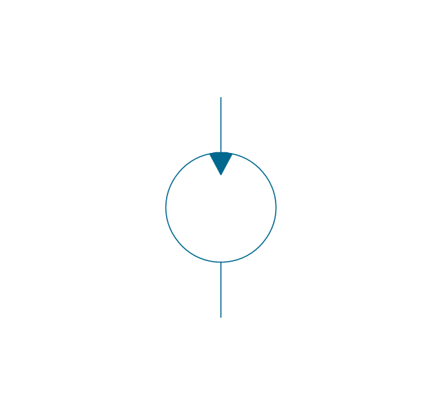
Pump, hydraulic

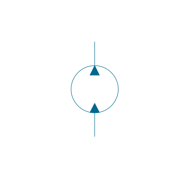
Motor, hydraulic
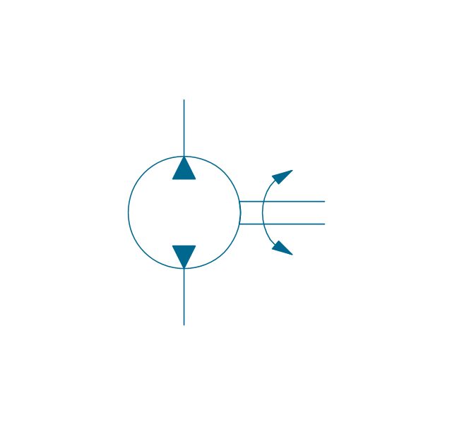
Pump-motor, hydraulic
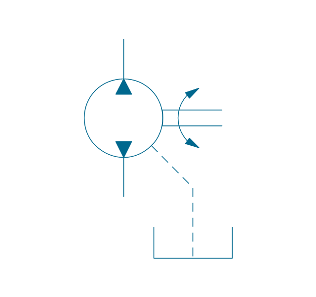
Pump, fixed, external drain
Pump, fixed, external drain
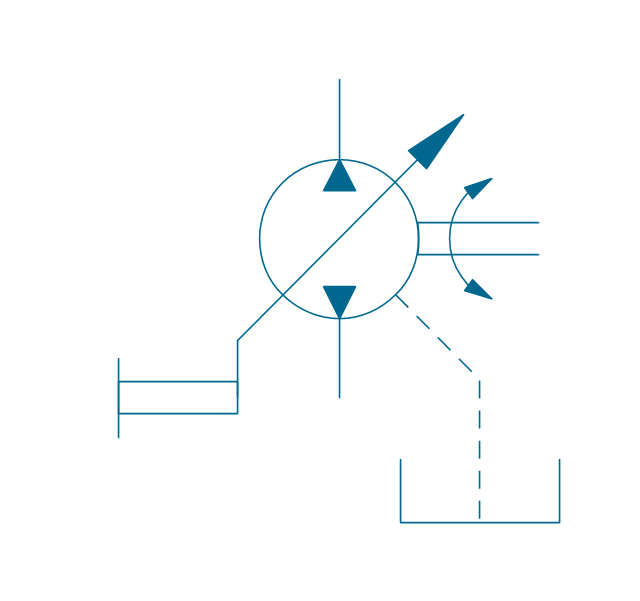
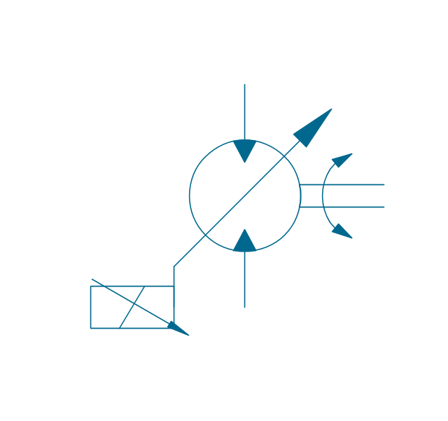
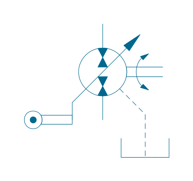
Pump, variable
Pump, variable, external drain

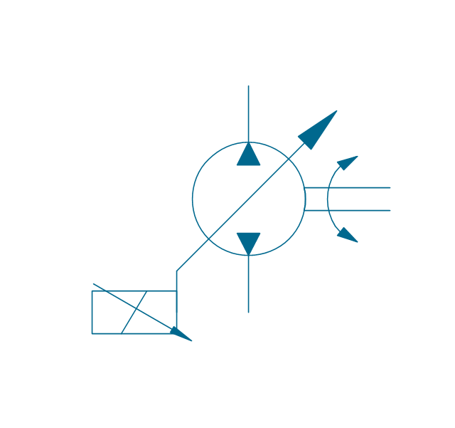
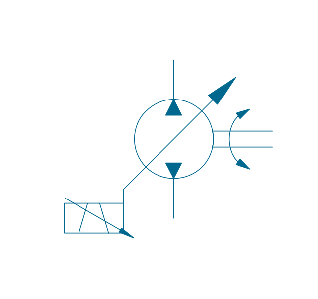
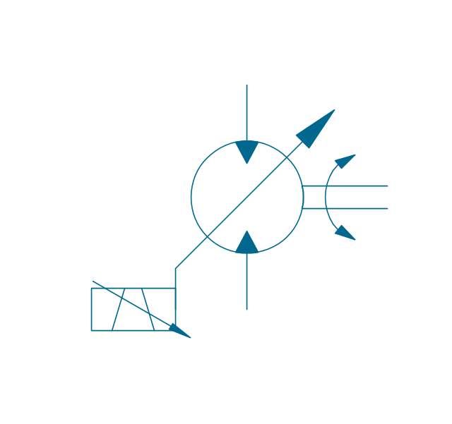
Pump, var., manual override

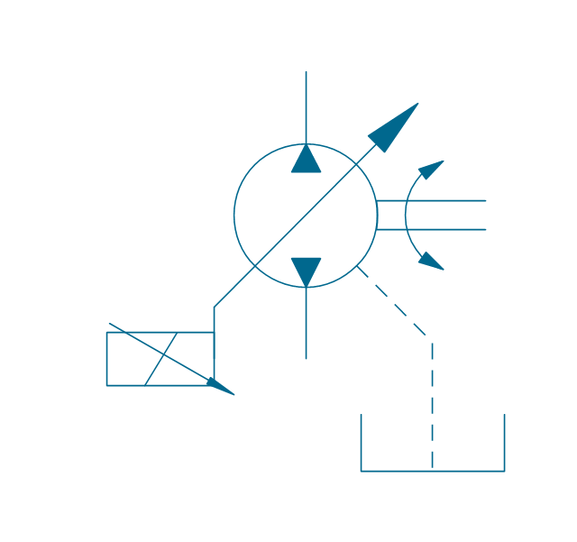
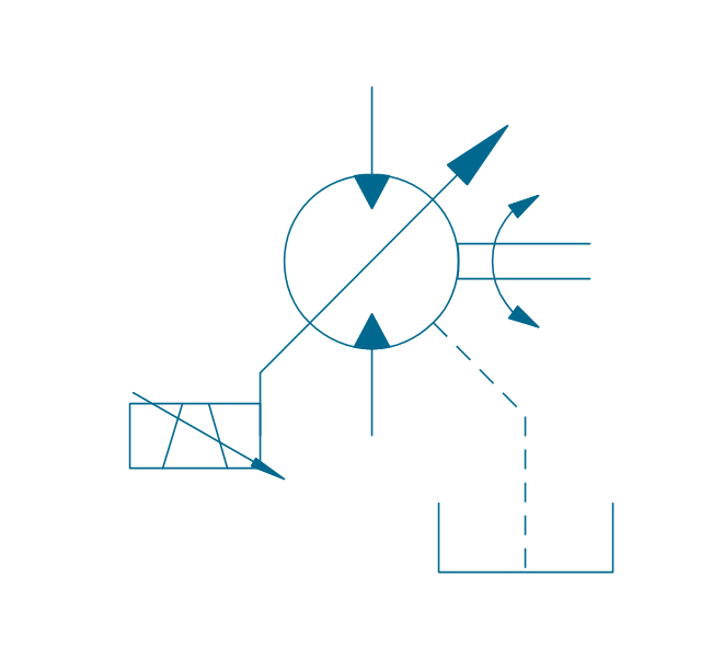
Pump, var., manual override, drain
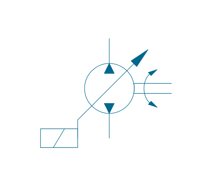
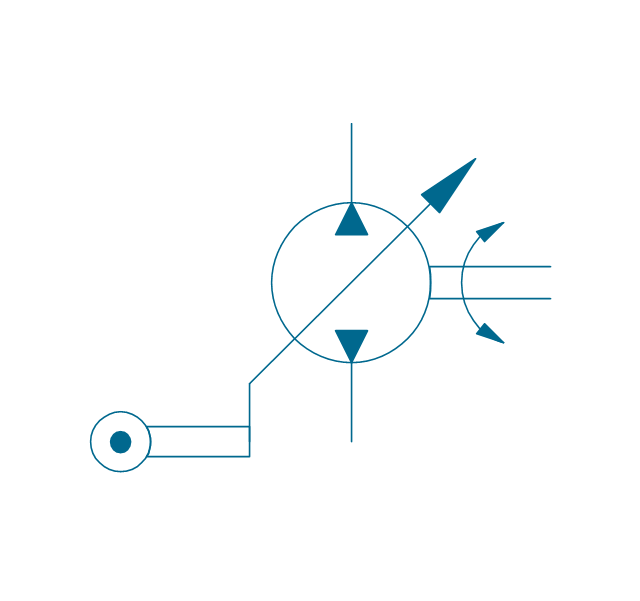
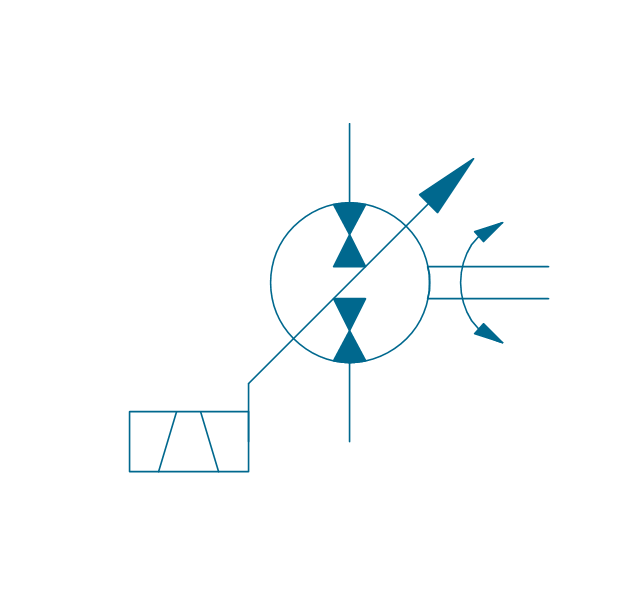
Pump, var., solenoid
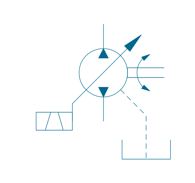
Pump, var., solenoid, drain

Pump, var., solenoid 2

Pump, var., solenoid 2, drain
Pump, var., var. solenoid
Pump, var., var. solenoid, drain
Pump, var., var. solenoid 2
Pump, var., var. solenoid 2, drain

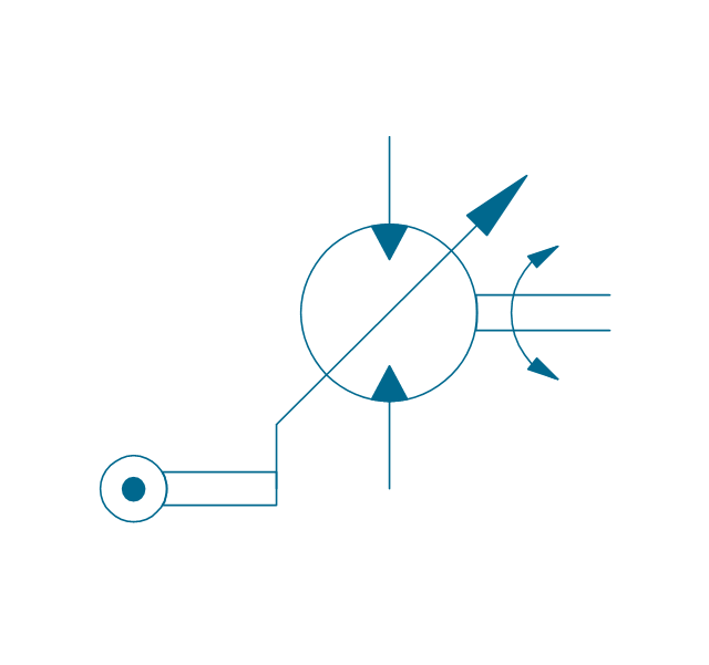
Pump, var., var., roller
Pump, var., roller, drain
Motor, fixed, external drain
Motor, fixed, external drain
Motor, variable
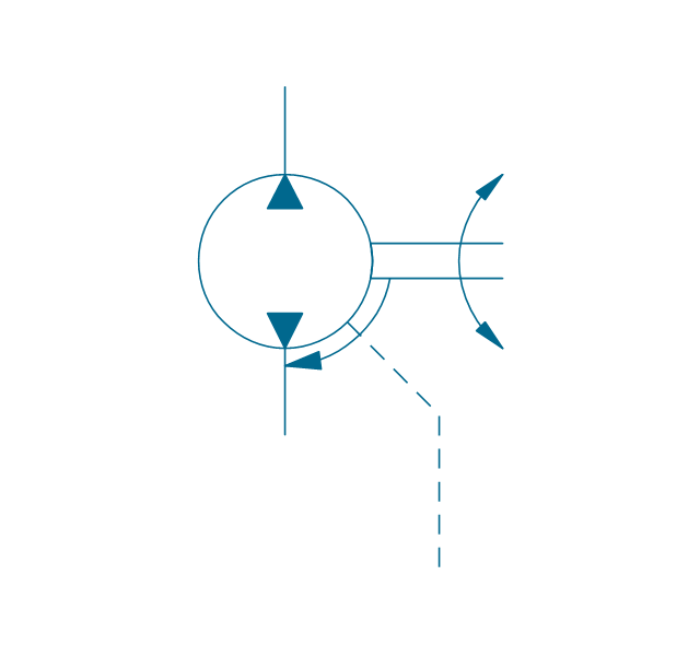
Motor, variable, external drain
Motor, var., manual override
Motor, var., manual override, drain

Motor, var., solenoid

Motor, var., solenoid, drain

Motor, var., solenoid 2
Motor, var., solenoid 2, drain
Motor, var., var. solenoid
Motor, var., var. solenoid, drain

Motor, var., var. solenoid 2
Motor, var., var. solenoid 2, drain
Motor, var., var., roller
Motor, var., roller, drain
Pump-motor, fixed, external drain
Pump-motor, fixed, external drain
Pump-motor, variable
Pump-motor, variable, external drain
Pump-motor, var., manual override
Pump-motor, var., manual override, drain
Pump-motor, var., solenoid

Pump-motor, var., solenoid, drain

Pump-motor, var., solenoid 2
Pump-motor, var., solenoid 2, drain
Pump-motor, var., var. solenoid
Pump-motor, var., var. solenoid, drain

Pump-motor, var., var. solenoid 2

Pump-motor, var., var. solenoid 2, drain
Pump-motor, var., var., roller
Pump-motor, var., roller, drain
Pump, fixed 2
Pump, fixed 2, drain
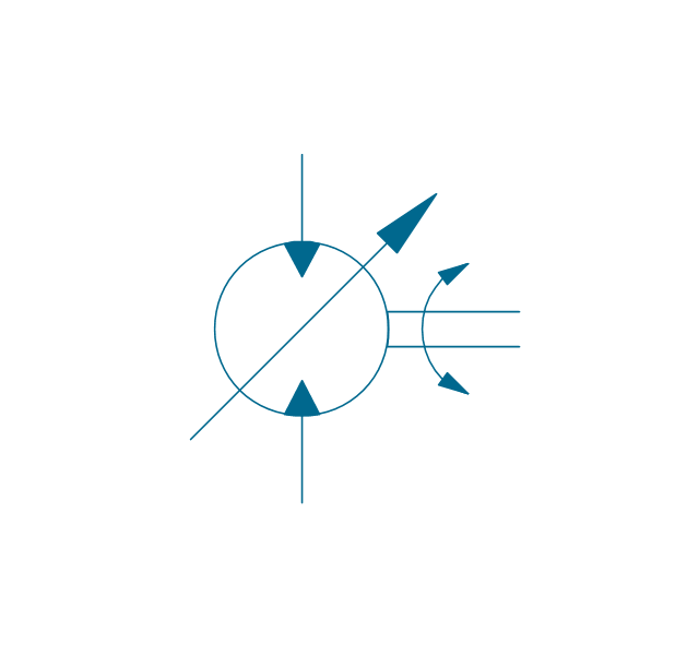
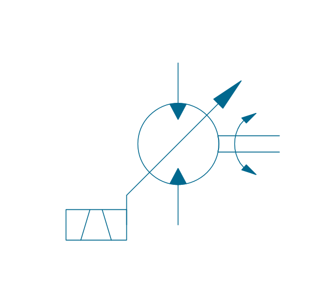
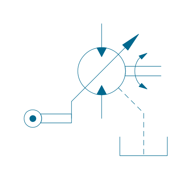
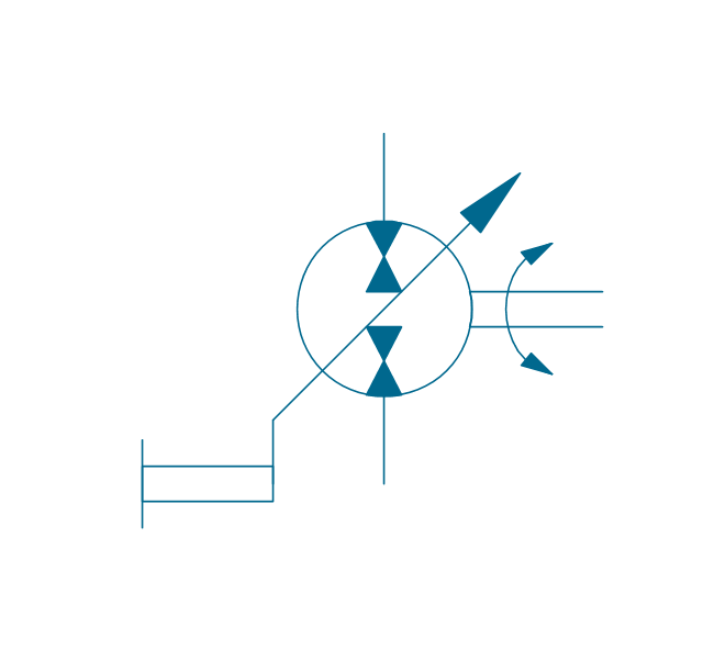
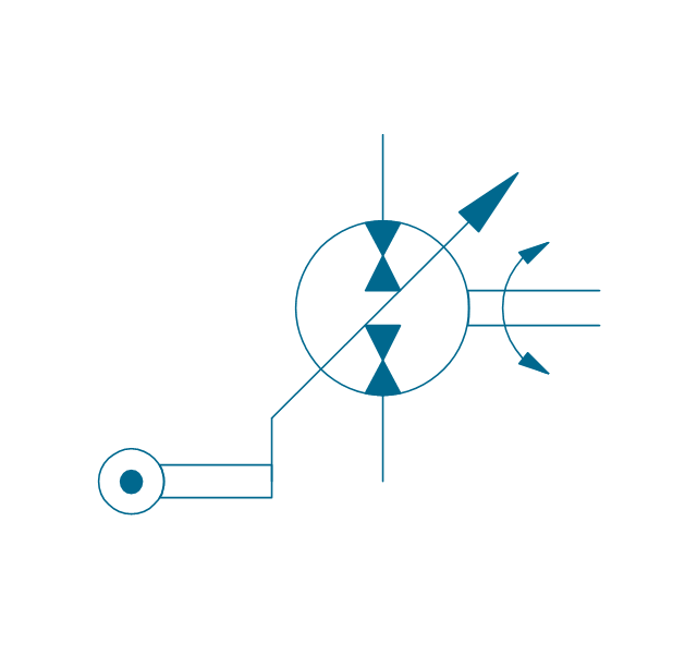
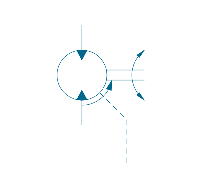
Pump, variable (sgl side)
-hydraulic-pumps-and-motors---vector-stencils-library.png--diagram-flowchart-example.png)
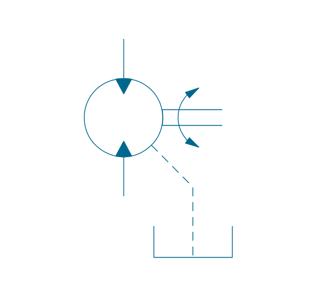
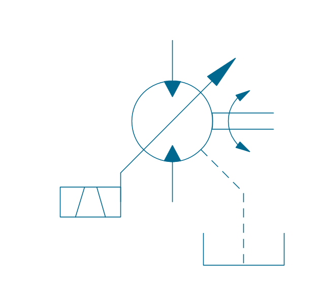
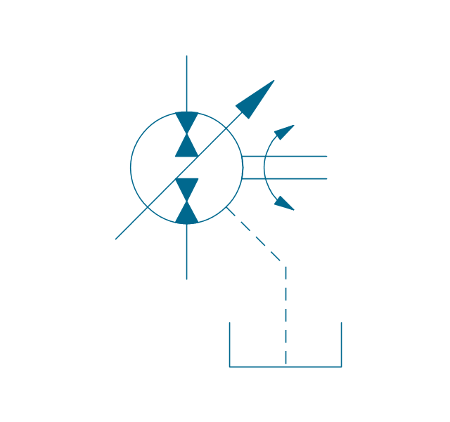
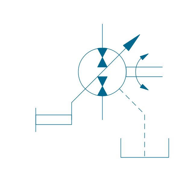
Pump, variable (sgl side), drain
,-drain-hydraulic-pumps-and-motors---vector-stencils-library.png--diagram-flowchart-example.png)
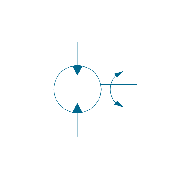
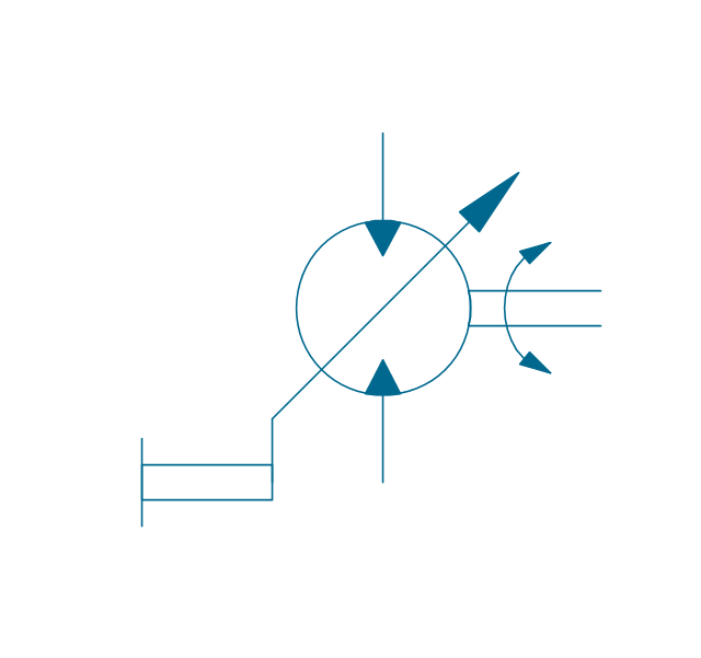
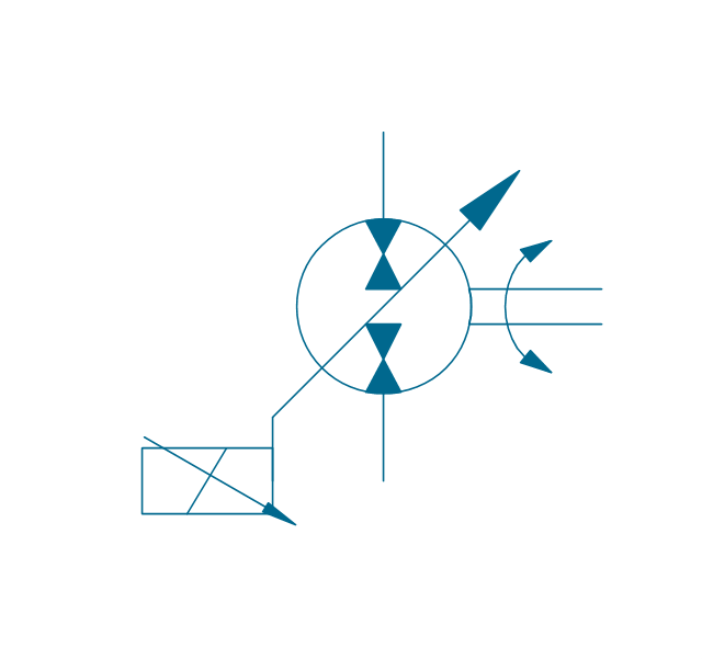
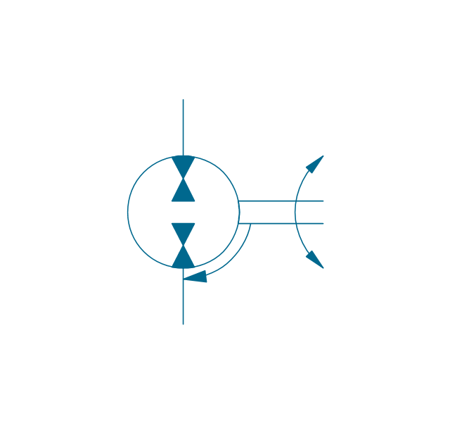
Pump, variable (dbl side)
-hydraulic-pumps-and-motors---vector-stencils-library.png--diagram-flowchart-example.png)
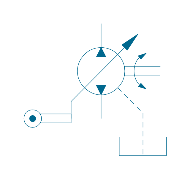
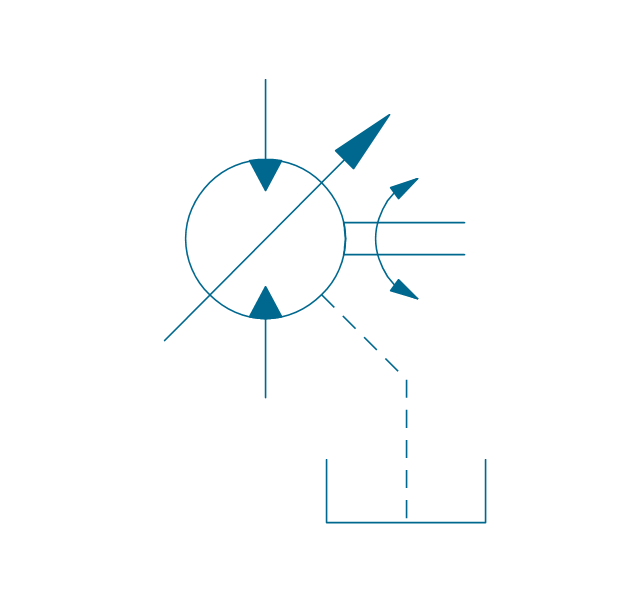
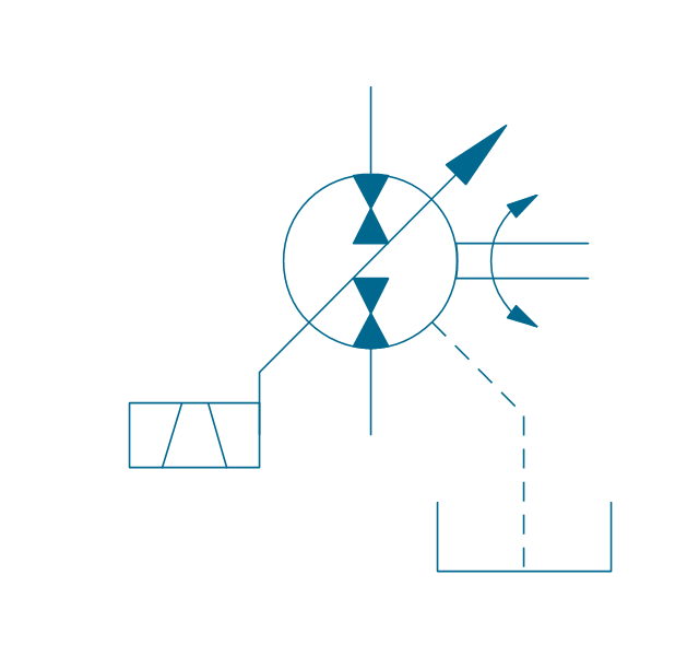
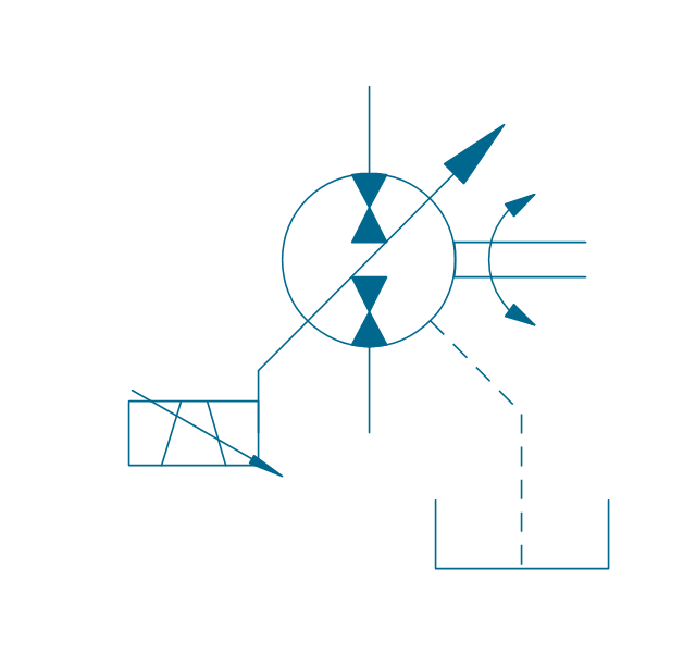
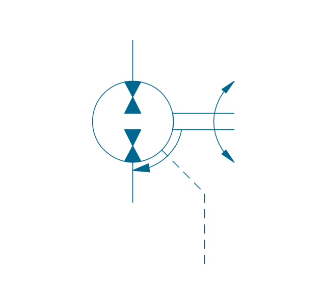
Pump, variable (dbl side), drain
,-drain-hydraulic-pumps-and-motors---vector-stencils-library.png--diagram-flowchart-example.png)
Motor, fixed 2
Motor, variable (sgl side)
-hydraulic-pumps-and-motors---vector-stencils-library.png--diagram-flowchart-example.png)
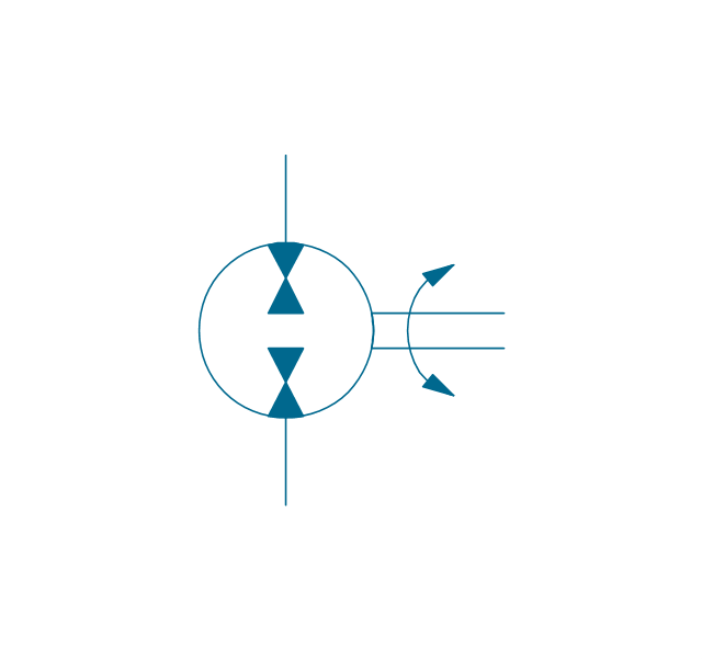
Motor, variable (dbl side)
-hydraulic-pumps-and-motors---vector-stencils-library.png--diagram-flowchart-example.png)
Motor, fixed 2, drain
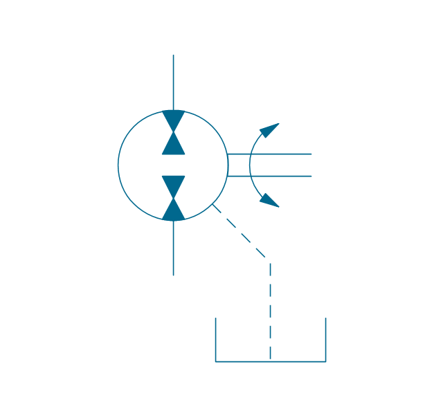
Motor, variable (sgl side), drain
,-drain-hydraulic-pumps-and-motors---vector-stencils-library.png--diagram-flowchart-example.png)
Motor, variable (dbl side), drain
,-drain-hydraulic-pumps-and-motors---vector-stencils-library.png--diagram-flowchart-example.png)
Pump-motor, fixed 2
Pump-motor, fixed 2, drain
Pump-motor, variable (sgl side)
-hydraulic-pumps-and-motors---vector-stencils-library.png--diagram-flowchart-example.png)
Pump-motor, variable (sgl side), drain
,-drain-hydraulic-pumps-and-motors---vector-stencils-library.png--diagram-flowchart-example.png)
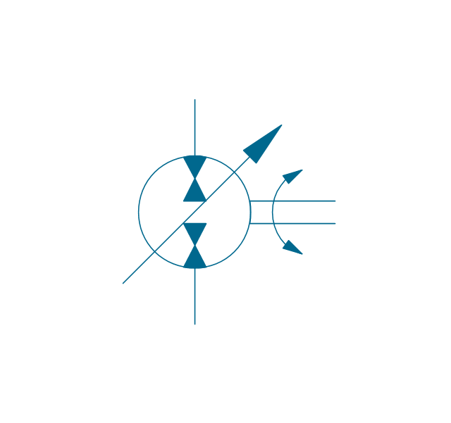
Pump-motor, variable (dbl side)
-hydraulic-pumps-and-motors---vector-stencils-library.png--diagram-flowchart-example.png)
Pump-motor, variable (dbl side), drain
,-drain-hydraulic-pumps-and-motors---vector-stencils-library.png--diagram-flowchart-example.png)
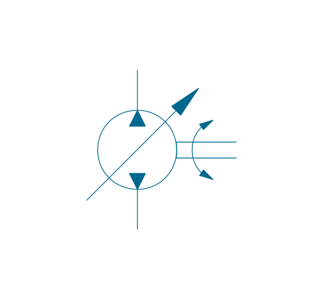
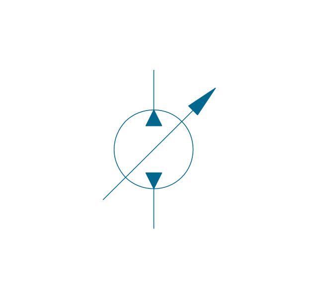
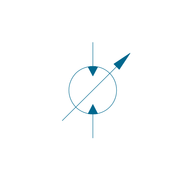
Pump, variable displacement
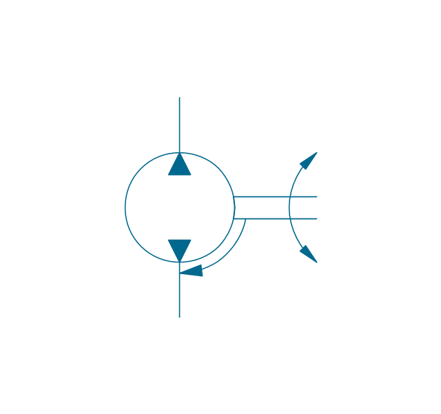
Motor, variable displacement
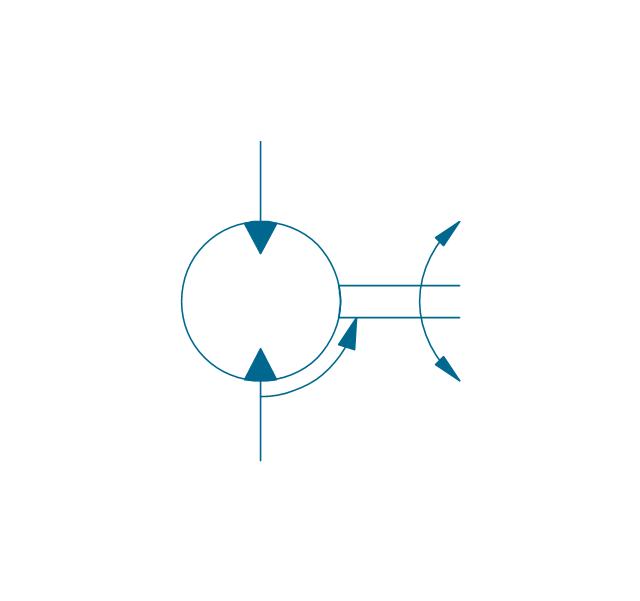
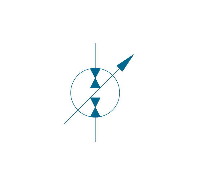
Pump-motor, variable displacement
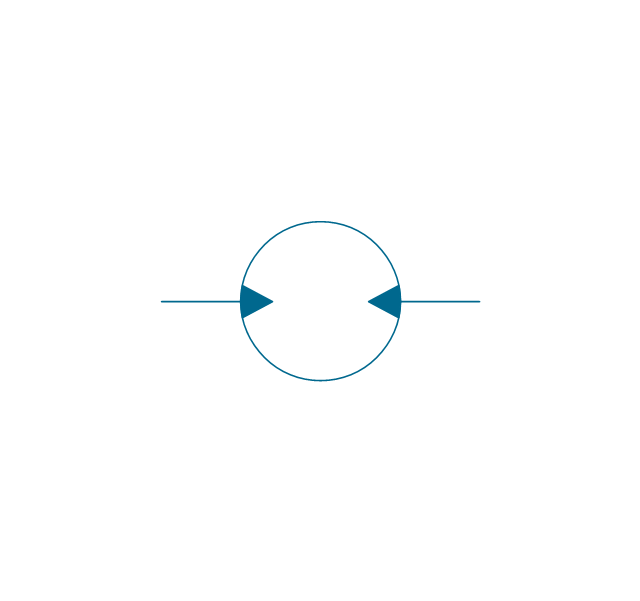
Floating motor
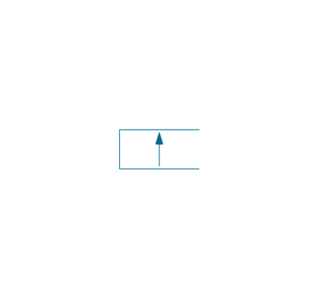
Pressure compensator
"A hydraulic circuit is a system comprising an interconnected set of discrete components that transport liquid. The purpose of this system may be to control where fluid flows (as in a network of tubes of coolant in a thermodynamic system) or to control fluid pressure (as in hydraulic amplifiers).
... hydraulic circuit theory works best when the elements (passive component such as pipes or transmission lines or active components such as power packs or pumps) are discrete and linear. This usually means that hydraulic circuit analysis works best for long, thin tubes with discrete pumps, as found in chemical process flow systems or microscale devices." [Hydraulic circuit. Wikipedia]
The engineering drawing example "Hydraulic circuits" was redrawn using ConceptDraw PRO diagramming and vector drawing software from the Wikimedia Commons file: Hydraulic circuits.png.
[commons.wikimedia.org/ wiki/ File:Hydraulic_ circuits.png]
This file is licensed under the Creative Commons Attribution-Share Alike 3.0 Unported license.
[creativecommons.org/ licenses/ by-sa/ 3.0/ deed.en]
The engineering drawing example "Hydraulic circuits" is included in the Mechanical Engineering solution from the Engineering area of ConceptDraw Solution Park.
Hydraulic circuit schematic

HelpDesk
How to Create a Mechanical Diagram

The vector stencils library "Valve assembly" contains 141 symbols of pressure and flow regulators, flow direction indicators, controls, and symbols to design flow paths of control valves.
Use these valve assembly shapes to design the engineering drawings of hydraulic and pneumatic valve assemblies in fluid power systems.
"Control valves are valves used to control conditions such as flow, pressure, temperature, and liquid level by fully or partially opening or closing in response to signals received from controllers that compare a "setpoint" to a "process variable" whose value is provided by sensors that monitor changes in such conditions.
The opening or closing of control valves is usually done automatically by electrical, hydraulic or pneumatic actuators. Positioners are used to control the opening or closing of the actuator based on electric, or pneumatic signals.
A control valve consists of three main parts in which each part exist in several types and designs: Valve's actuator, Valve's positioner, Valve's body.
" [Control valves. Wikipedia]
The shapes example "" was created using the ConceptDraw PRO diagramming and vector drawing software extended with the Mechanical Engineering solution from the Engineering area of ConceptDraw Solution Park.
Valve assembly symbols

- Technical Engineering Drawing Symbols Hydraulic
- Hydraulic Pump Diagram Software
- Draw A Circuit Diagram Of A Hydraulic Engineering System
- Hydraulic circuits | Design elements - Hydraulic pumps and motors ...
- Mechanical Drawing Symbols | Mechanical Engineering ...
- Hydraulic Pump Drawing
- Drawing Symbol Of Pump Coupled To Motor
- Engineering | Piping and Instrumentation Diagram Software ...
- Hydraulic circuits | Mechanical Drawing Symbols | Apparatus for ...
- Mechanical Drawing Symbols | Hydraulic pumps and motors ...
- Basic Hydraulic System Single Line Diagram
- Mechanical Drawing Symbols | Process Flow Diagram Symbols ...
- Free Hydraulic System Design Software
- Hydraulic Motors Engineering Drawings
- Sketch Of Basic Elements Of Hydraulik System
- Technical Drawing Software | Mechanical Engineering | Engineering ...
- Hydraulic circuits | Technical Drawing Software | Engineering ...
- Hydraulic Pneumatic Schematic Engineering Drawings
- How To Draw Hydraulics Circuit Diagrams
- Pneumatic Or Hydraulic Control System Diagram Visio