 Mechanical Engineering
This solution extends ConceptDraw PRO v.9 mechanical drawing software (or later) with samples of mechanical drawing symbols, templates and libraries of design elements, for help when drafting mechanical engineering drawings, or parts, assembly, pneumatic,
This example engineering drawing showing the hydraulic directional control valve usage with floating motor and pressure compensated pump is redesigned using the ConceptDraw PRO diagramming and vector drawing software from the Wikimedia Commons file: DCV 17.jpg.
[commons.wikimedia.org/ wiki/ File:DCV_ 17.jpg]
This file is licensed under the Creative Commons Attribution-Share Alike 3.0 Unported license.
[creativecommons.org/ licenses/ by-sa/ 3.0/ deed.en]
"Directional control valves are one of the most fundamental parts in hydraulic machinery as well and pneumatic machinery. They allow fluid flow into different paths from one or more sources. They usually consist of a spool inside a cylinder which is mechanically or electrically controlled. The movement of the spool restricts or permits the flow, thus it controls the fluid flow. ...
The spool (sliding type) consists of lands and grooves.The lands block oil flow through the valve body. The grooves allow oil or gas to flow around the spool and through the valve body. There are two fundamental positions of directional control valve namely normal position where valve returns on removal of actuating force and other is working position which is position of a valve when actuating force is applied. There is another class of valves with 3 or more position that can be spring centered with 2 working position and a normal position. ...
Directional control valves can be classified according to:
(1) number of ports;
(2) number of positions;
(3) actuating methods;
(4) type of spool." [Directional control valve. Wikipedia]
The fluid power equipment drawing example "Directional control valve" is included in the Mechanical Engineering solution from the Engineering area of ConceptDraw Solution Park.
Hydraulic equipment schematic

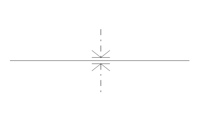
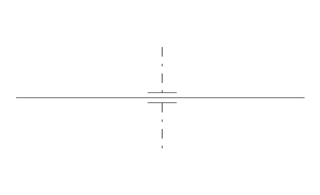
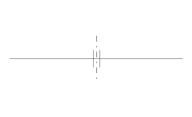
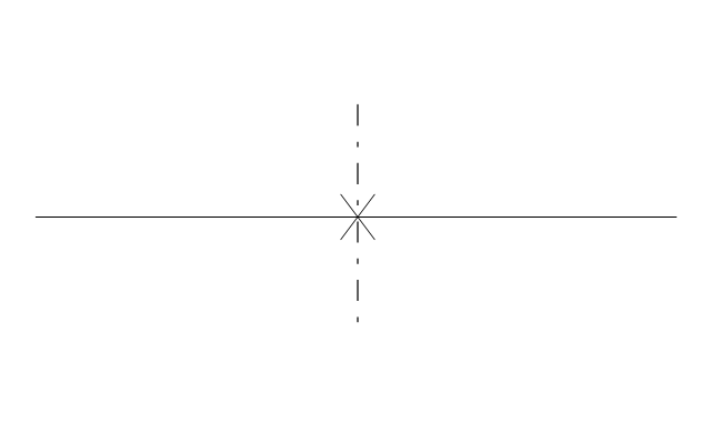
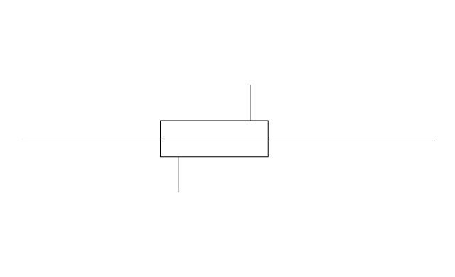
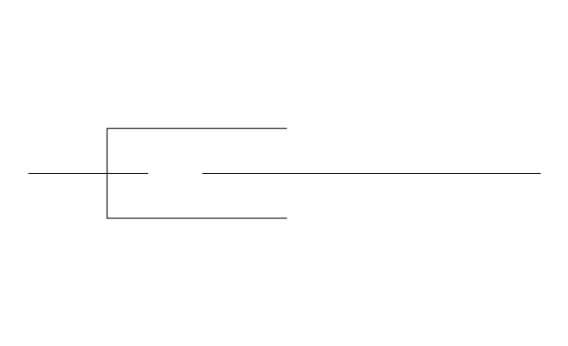
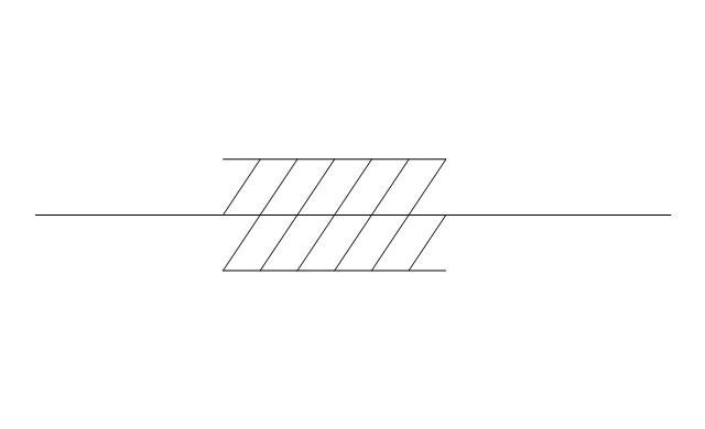
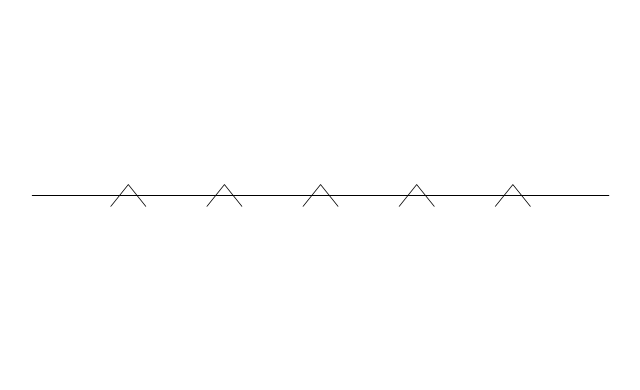
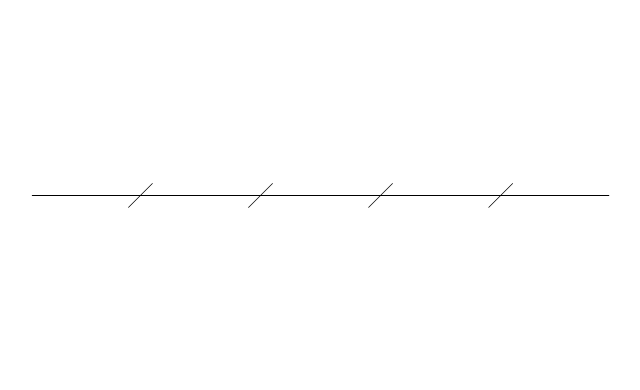
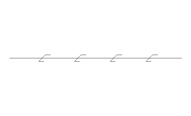
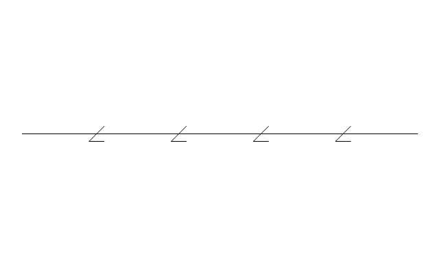
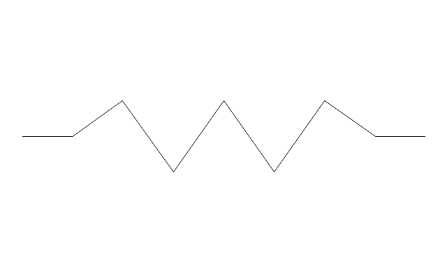
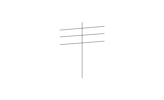
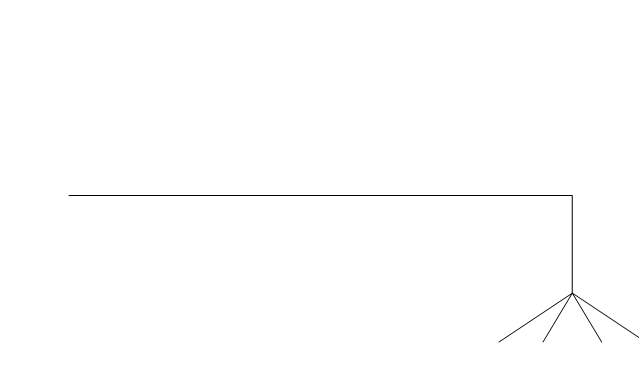
The vector stencils library "Pipes 2" contains 48 symbols of pipes. Use it for drawing plumbing and piping building plans, schematic diagrams, blueprints, or technical drawings of waste water disposal systems, hot and cold water supply systems in the ConceptDraw PRO diagramming and vector drawing software extended with the Plumbing and Piping Plans solution from the Building Plans area of ConceptDraw Solution Park.
Crossing
Junction
Basic support
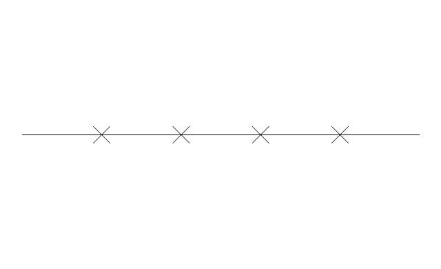
Guide 1
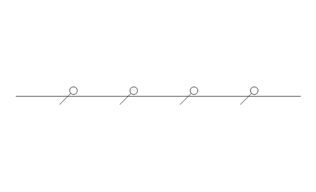
Guide 2
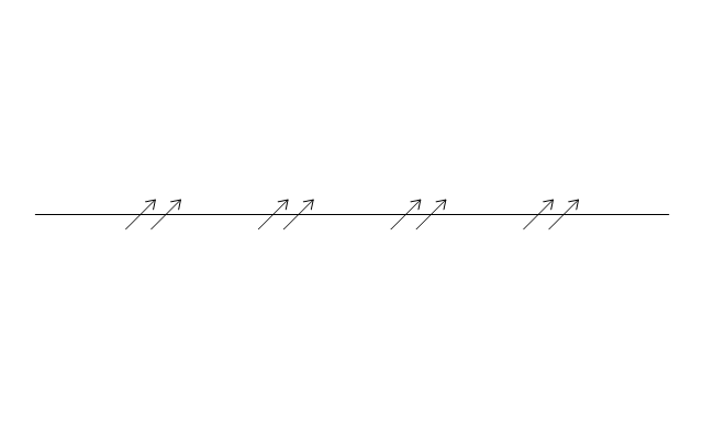
Guide 3
Stopper
Anchor
Support / anchor
Hunger
Cross
Double branch
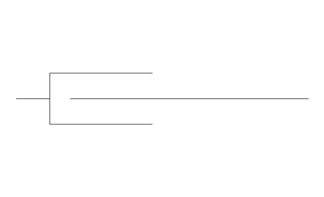
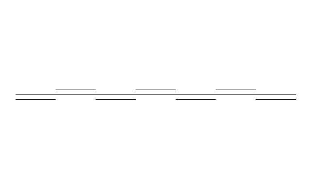
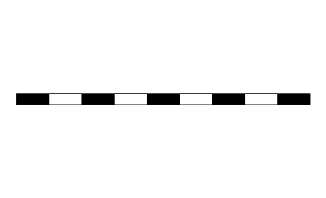
Jacketed
Sleeved

Sleeve joint
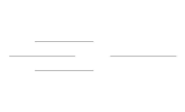
Expansion sleeve joint
Lagged
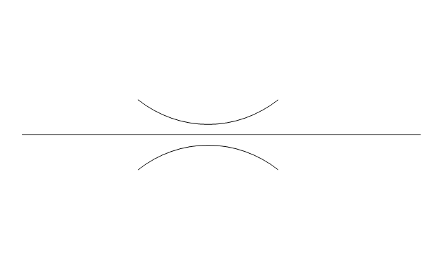
Bellows
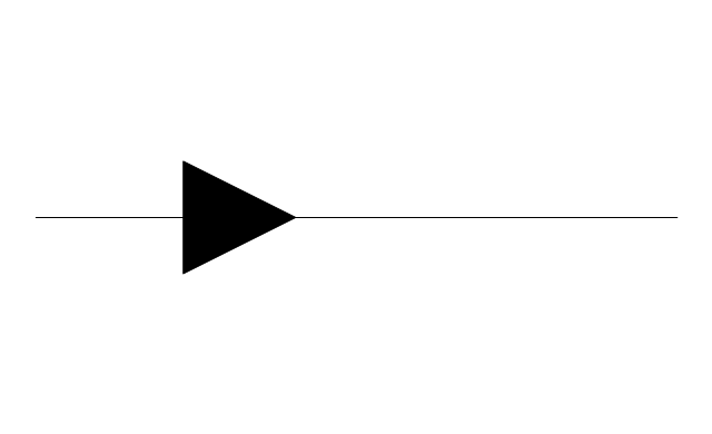
Flow indication
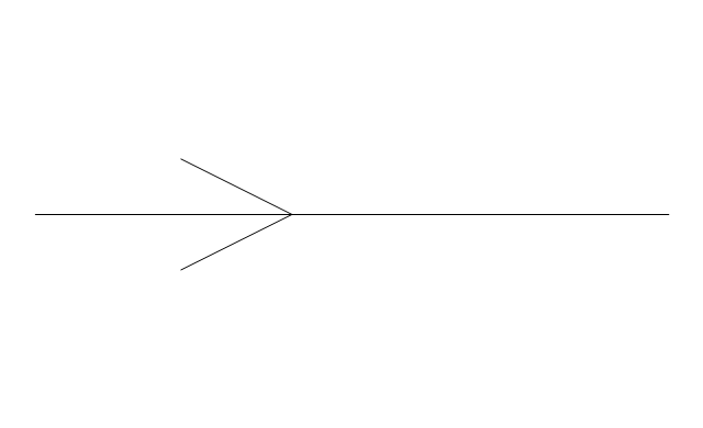
Flow indication 2
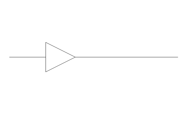
Reducer
Reducer,arrow
Pipe bore change
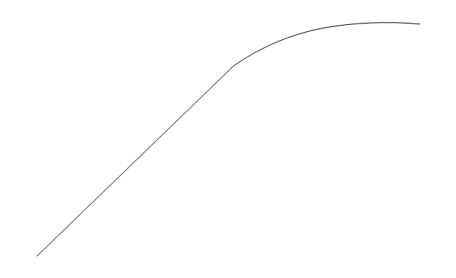
Flexibility provision
Sleeve extension
Flow restrictor
Elbow 45
Elbow 90
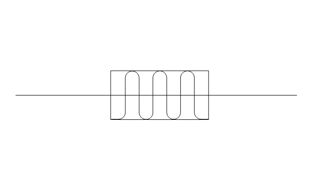
Heated or cooled
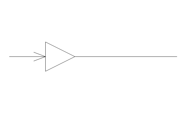
Pneumatic line
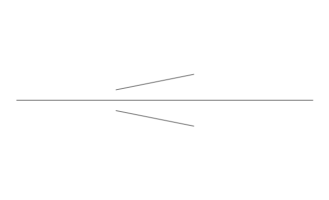
Signal line
Electric line
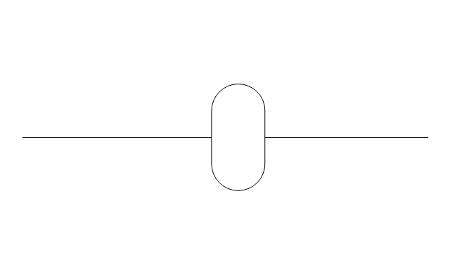
Hydraulic line
Capillary line
Internal connection
Route radiation
Mechanical linkage
Electrical device
Vibratory device
Weight device
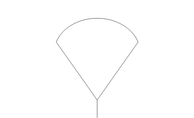
Spray device
Rotary motion
Stirring / fan
Access points

Trap
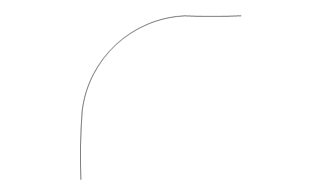
Expansion loop
Flexible hose
Flexible hose, flanged
- Hydraulic Pipe Joint Machine Drawing
- Hydraulic Joint Drawing
- Hydraulic Joint Sketch
- Butt weld geometry | Hydraulic circuits | Technical drawing ...
- Hydraulic Pipe Joints Mechanical Drawing
- Hydraulic Joint In Drawing
- What Are The Uses Of Hydraulic Joint In Engineering Drawing
- Design elements - Valves and fittings | Hydraulic Turning Joint Symbol
- Mechanical Drawing Symbols | Hydraulic pumps and motors ...
- Mechanical Drawing Symbols | Elements location of a welding ...
- Technical drawing - Machine parts assembling | Mechanical ...
- Draw Hydraulic Circuit For A Hydraulic Planner
- Mechanical Engineering | Interior Design Piping Plan - Design ...
- Technical Drawing Software | Mechanical Drawing Symbols ...
- Mechanical Drawing Symbols | Mechanical Design Software ...
- Mechanical Drawing Symbols | Hydraulic 4-ported 3-position valve ...
- How To Draw A Mechanical Engineering Schematics
- Hydraulic Pneumatic Symbols Drawing Template Stencil
- Drawing Sketches Of Pneumatics And Hydraulic Mechanical Systems
- Mechanical Drawing Symbols | Technical Drawing Software ...