ConceptDraw DIAGRAM ER Diagram Tool
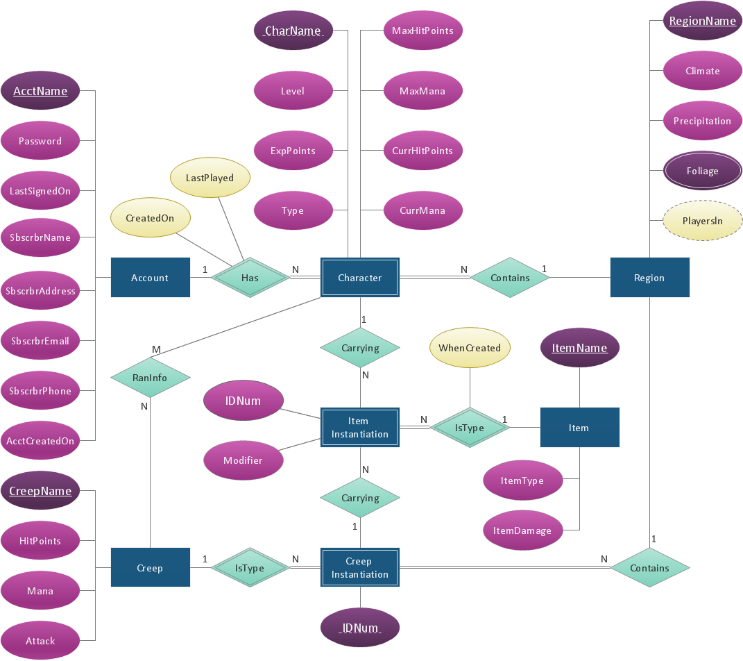
Entity-relationship model, also called ER-model, is the main tool of domain modeling on the stage of conceptual design. The modeling of domain data structures is based on the use of graphical tools - Entity-Relationship diagrams (ER-diagrams). The core concepts of ER-Diagram are entity, attribute and relationship. ER-diagram lets visually represent the entities, helps effectively document all properties of designed system and to detail the data storages. To represent the elements at ER-model are commonly used Chen’s notation and Crow’s foot notation, each has its pros and cons. The entity on ER-diagram is represented in the form of rectangle, which specifies its name. An attribute is a property of the entity and relationship is an interaction between the entities. The relationship between two entities is called binary, between more than two entities - ternary. Specific software, such as ConceptDraw DIAGRAM with Entity-Relationship Diagram (ERD) solution from ConceptDraw Solution Park is helpful for easy creation Entity-Relationship Diagrams.
 Line Graphs
The Line Graphs solution extends the capabilities of ConceptDraw DIAGRAM with professionally designed templates, samples, and a library of vector stencils for drawing perfect Line Graphs. Turn your data into a Line Graph with ConceptDraw DIAGRAM software and use it in any document, presentation, report, share it with your team, etc. Building several curves on the same chart, it is recommended to paint them with different colors, this will allow to separate them visually from each other and will make it easier the data comparison.
- UML Use Case Diagram Example. Registration System | UML ...
- Cross-Functional Process Map Template | Process Flowchart
- Basic Flowchart Examples | Basic Diagramming | Form Maker ...
- Process Flowchart | Investment and construction application ...
- UML Use Case Diagram Example. Registration System | UML ...
- How to Create a BPMN Diagram Using ConceptDraw PRO | The ...
- UML Use Case Diagram Example. Registration System | Event ...
- Business Process Elements: Swimlanes | Cross-Functional Flowchart
- Example Process Flow Chart
- UML Use Case Diagram Example. Registration System | Example of ...
