Mechanical Drawing Symbols

Electrical Symbols — VHF UHF SHF

Electrical Symbols, Electrical Schematic Symbols

Electrical Symbols — Terminals and Connectors

How To use House Electrical Plan Software


The vector stencils library "Valves and fittings" contains 104 symbols of valve components.
Use these icons for drawing industrial piping systems; process, vacuum, and fluids piping; hydraulics piping; air and gas piping; materials distribution; and liquid transfer systems in the ConceptDraw PRO software extended with the Chemical and Process Engineering solution from the Chemical and Process Engineering area of ConceptDraw Solution Park.
www.conceptdraw.com/ solution-park/ engineering-chemical-process
Electrically bonded

Bursting disc

Flame arrester

Strainer

Separator

Exhaust silencer

Bell mouth

Exhaust head

Hydrant

Drain silencer

Liquid seal open/closed

Y strainer

Gate valve

Globe valve

Globe valve 2

Globe valve 3

Screw-down valve

Lock-shield valve

Reel valve

Check valve

Check valve 2

Check valve 3

Screw-down check valve

Stop check valve

Diaphragm valve

Diaphragm valve 2

Diaphragm valve 3

Powered valve

Powered valve 2

Powered valve 3

Needle valve

Needle valve 2

Needle valve 3

Relief valve

Relief valve 2

Relief valve 3

Angle valve

Angle valve 2

Angle valve 3

Angle valve 4

Float operated valve

Float operated valve 2

Flanged valve

Butterfly valve

Butterfly valve 2

Wedge gate valve

Parallel slide valve

Ball valve

Ball valve 2

Ball valve 3

Relief angle valve vacuum

Relief angle valve pressure

Reducing valve

Reducing valve 2

Plug valve 3 way

Plug valve L point

Plug valve 2

Plug valve

Plug valve straight through

Plug valve T point

3-way plug valve

3-way plug valve 2

3-way plug valve 3

Mixing valve

Valve Manifold

Characterized port valve

Reducer

Reducer 2

General joint

Butt weld

Butt weld 2

Butt weld 3

Butt weld 4

Flanged/ bolted

Soldered / solvent

Soldered / solvent 2

Screwed joint

Screwed joint 2

Screwed joint 3

Socket and spigot

Socket and spigot 2

Socket and spigot 3

Sleeve

Sleeve 2

Screwed sleeve

Screwed sleeve 2

Socket weld

Socket weld 2

Swivel joint

Swivel joint 2

Swivel joint 3

End cap

End cap butt welded

End cap screwed

End cap socket and spigot

End cap fillet welded

End cap screwed and plugged

End cap quick release

End cap flanged and bolted

End cap flanged and bolted 2

Electrically insulated

Tundish

Syphon drain

Open vent

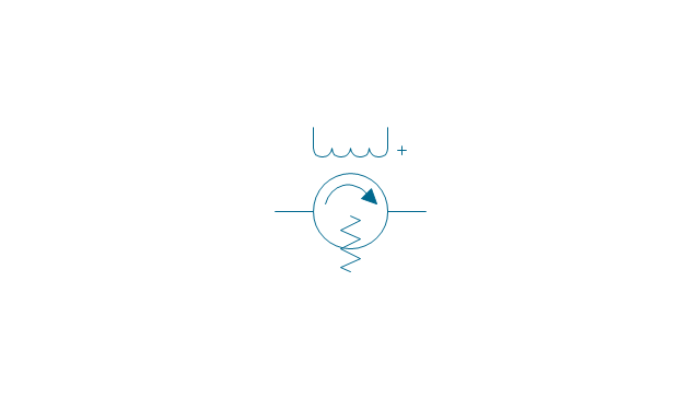
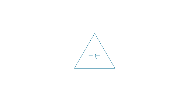
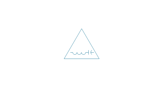
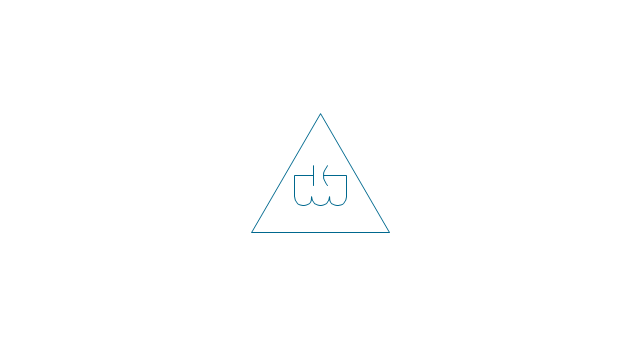
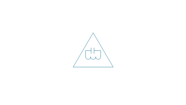
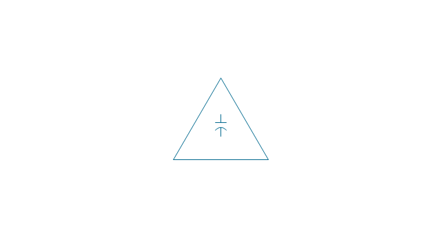
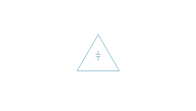
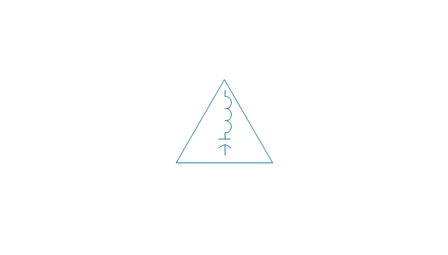
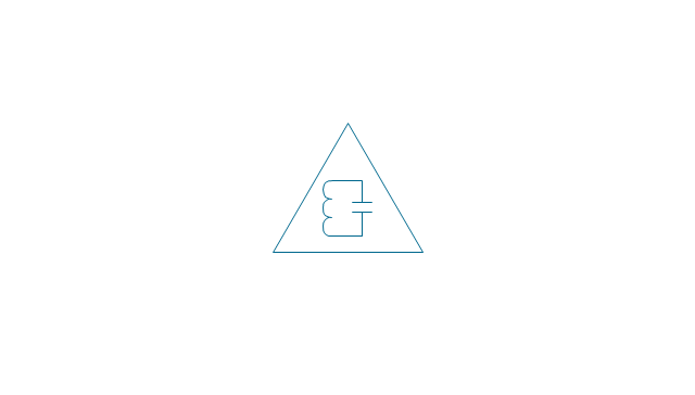
The vector stencils library "VHF UHF SHF" contains 52 symbols for VHF, UHF, and SHF circuit design, including capacitance measurers, nonreciprocal devices, modulators, phase shifters, field polarization devices, and filters.
Use these shapes for drawing VHF, UHF and SHF diagrams in the ConceptDraw PRO diagramming and vector drawing software extended with the Electrical Engineering solution from the Engineering area of ConceptDraw Solution Park.
www.conceptdraw.com/ solution-park/ engineering-electrical
Use these shapes for drawing VHF, UHF and SHF diagrams in the ConceptDraw PRO diagramming and vector drawing software extended with the Electrical Engineering solution from the Engineering area of ConceptDraw Solution Park.
www.conceptdraw.com/ solution-park/ engineering-electrical
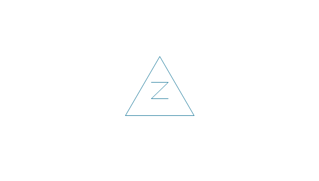
Discontinuity
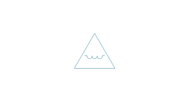
Equivalent series
Inductive reactance
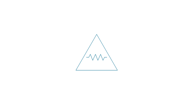
Resistance
Equivalent shunt
Inductive susceptance
Conductance
Slide screw tuner
E-H tuner

Multistub tuner
Mode suppressor
Rotary joint
Isolator
Phase shifter
Gyrator
Circulator fixed
Circulator reversible

Field polarization rotator
Field polarization amplitude modulator
Resonator
Mode filter
Phase shifter (matched)
-vhf-uhf-shf---vector-stencils-library.png--diagram-flowchart-example.png)
Ferrite bead ring
Capacitive reactance
Capacitive reactance 2

Inductance capacitance
Inductance capacitance 2

Inductance capacitance 3
Inductance capacitance 4
Capacitive susceptance
Capacitive susceptance 2
Inductance capacitance 5
Inductance capacitance 6

Inductance capacitance 7

Inductance capacitance 8
Directional coupler
Directional coupler 2
Balun
Balun 2
Frequency filter
Frequency filter, high-pass
Frequency filter, low-pass
Frequency filter, band-pass
Frequency filter, band-stop
Line stretcher, male
Line stretcher, female
Maser
Maser, amplifier
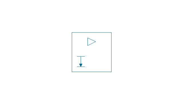
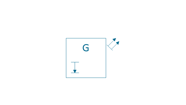
Laser
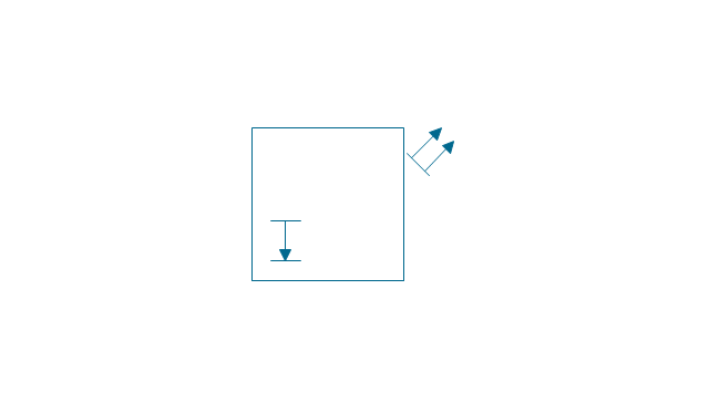
Laser, generator
Ruby laser
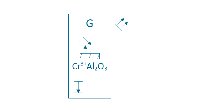
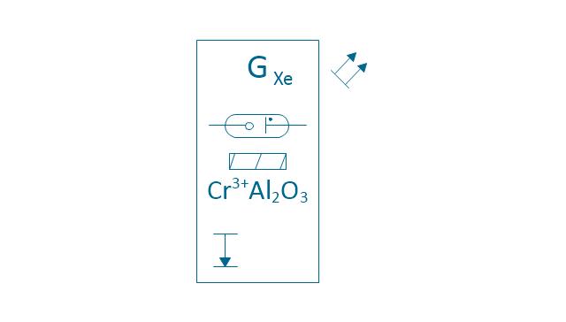
Ruby laser, Xenon lamp
Electrical Symbols — Thermo

Electrical Symbols — MOSFET

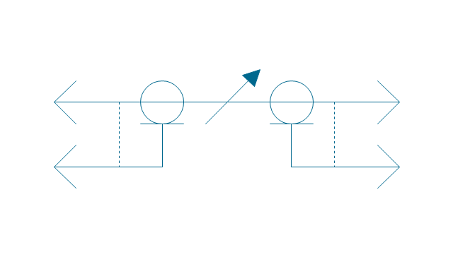
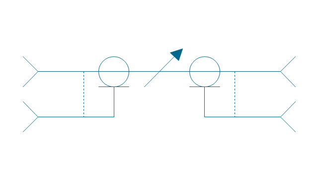
 Vehicular Networking
The Vehicular Networking solution extends the ConceptDraw DIAGRAM software functionality with specialized tools, wide variety of pre-made vector objects, collection of samples and templates in order to help network engineers design vehicular network diagrams for effective network engineering activity, visualize vehicular networks, develop smart transportation systems, design various types of vehicle network management diagrams, regional network diagrams, vehicular communication system diagrams, vehicular ad-hoc networks, vehicular delay-tolerant networks, and other network engineering schemes.
- How To Draw Building Plans | Hydrant Drafting Symbol
- Electrical Symbols, Electrical Diagram Symbols | Electrical Symbols ...
- Mechanical Engineering | Mechanical Drawing Symbols | How To ...
- Mechanical Engineering | Technical drawing - Machine parts ...
- Mechanical Drawing Symbols | Electrical Symbols, Electrical ...
- Lamps , acoustics, measuring instruments - Vector stencils library ...
- How To use House Electrical Plan Software | Process Flow Diagram ...
- Mechanical Drawing Symbols | Electrical Symbols, Electrical ...
- Process Flow Diagram Symbols | Electrical Symbols, Electrical ...
- Mechanical Drawing Symbols | Electrical Symbols, Electrical ...