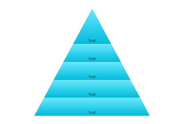
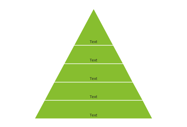
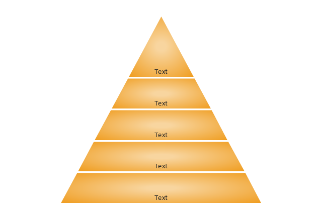
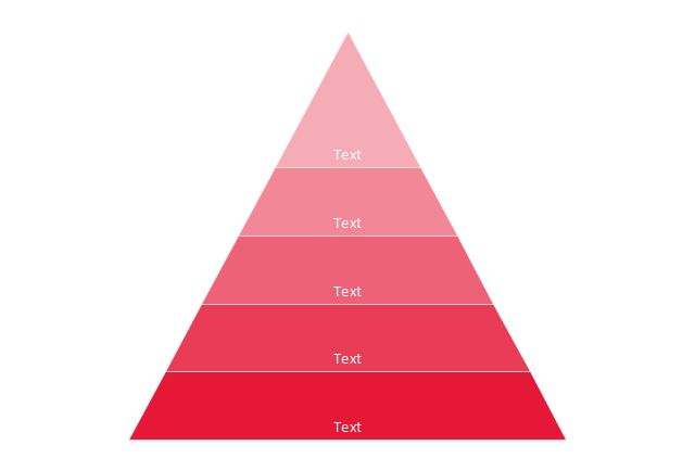
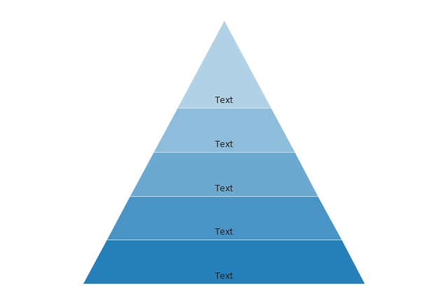
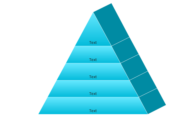
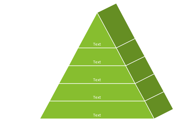
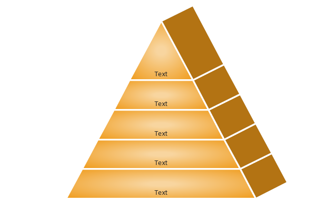
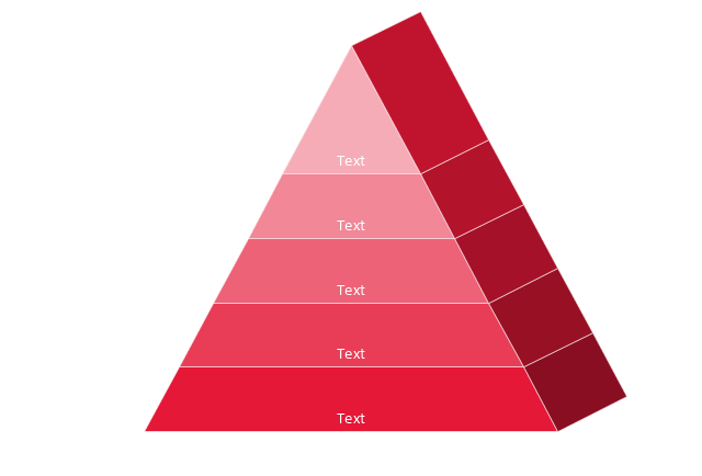
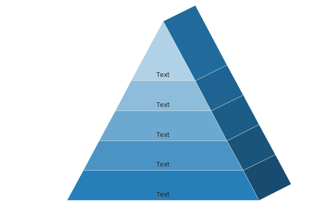
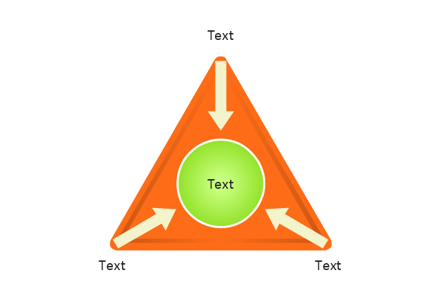
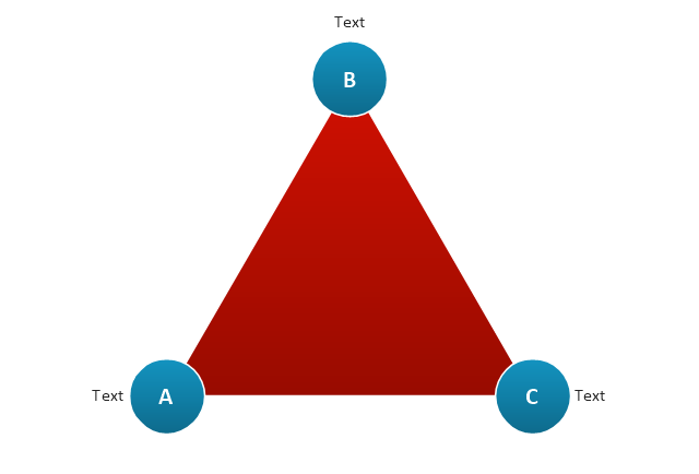
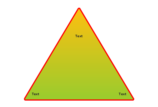
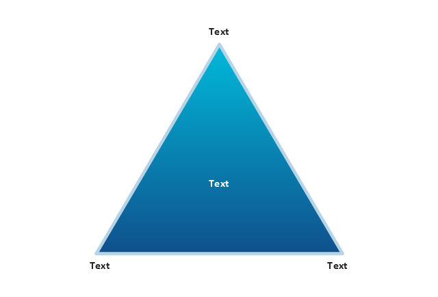
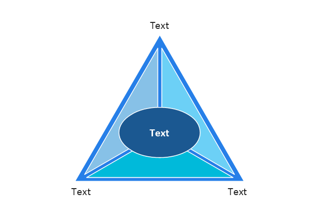
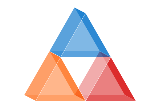
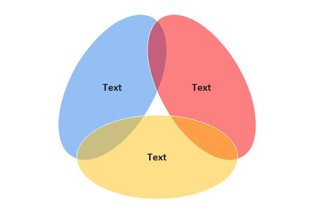
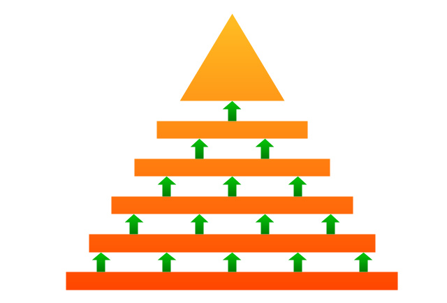
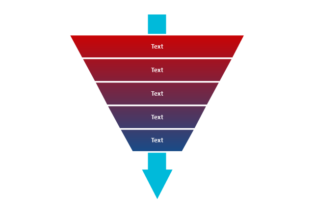
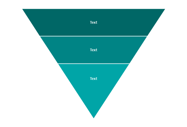
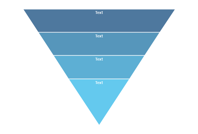
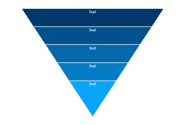
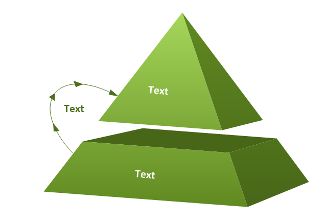
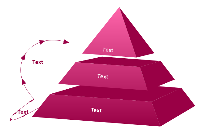
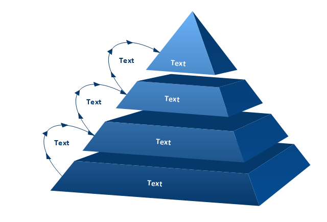
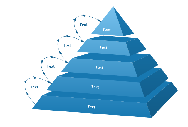
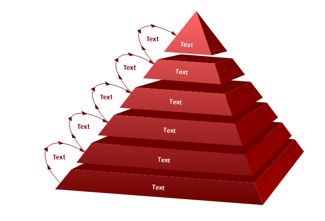
The vector stencils library "Pyramid diagrams" contains 28 templates of pyramid diagrams, triangle charts and triangular schemes.
Use these templates to create your pyramid diagrams in the ConceptDraw PRO diagramming and vector drawing software extended with the Pyramid Diagrams solution from the Marketing area of ConceptDraw Solution Park.
Use these templates to create your pyramid diagrams in the ConceptDraw PRO diagramming and vector drawing software extended with the Pyramid Diagrams solution from the Marketing area of ConceptDraw Solution Park.
HelpDesk
How to Draw a Pyramid Diagram in ConceptDraw PRO
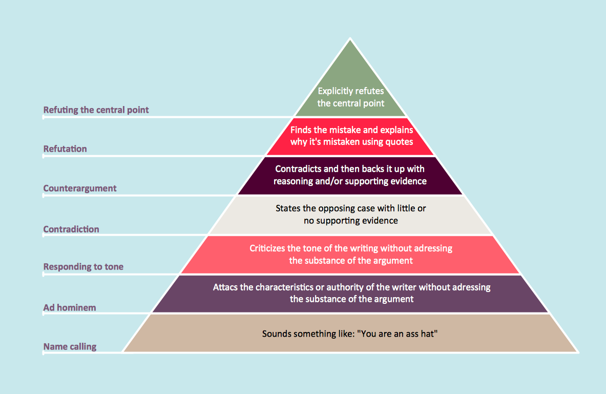
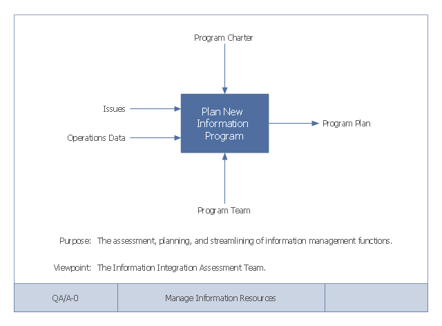
Pyramid diagram (triangle diagram) is used to represent data, which have hierarchy and basics. Due to the triangular form of diagram, each pyramid section has a different width. The width of the segment shows the level of its hierarchy. Typically, the top of the pyramid is the data that are more important than the base data. Pyramid scheme can be used to show proportional and hierarchical relationships between some logically related items, such as departments within an organization, or successive elements of any process. This type of diagram is often used in marketing to display hierarchical related data, but it can be used in a variety of situations. ConceptDraw PRO allows you to make a pyramid diagram, quickly and easily using special libraries.This example of a Top Level Context Diagram for an information system management process was redesigned from the Wikipedia file: IDEF Top-Level Context Diagram.jpg. [en.wikipedia.org/ wiki/ File:IDEF_ Top-Level_ Context_ Diagram.jpg]
"Graphical notation.
IDEF0 is a model that consists of a hierarchical series of diagrams, text, and glossary cross referenced to each other. The two primary modeling components are:
(1) functions (represented on a diagram by boxes), and
(2) data and objects that interrelate those functions (represented by arrows).
... the position at which the arrow attaches to a box conveys the specific role of the interface. The controls enter the top of the box. The inputs, the data or objects acted upon by the operation, enter the box from the left. The outputs of the operation leave the right-hand side of the box. Mechanism arrows that provide supporting means for performing the function join (point up to) the bottom of the box.
The IDEF0 process.
The IDEF0 process starts with the identification of the prime function to be decomposed. This function is identified on a “Top Level Context Diagram,” that defines the scope of the particular IDEF0 analysis. ... From this diagram lower-level diagrams are generated." [IDEF0. Wikipedia]
The IDEF0 diagram example "Top-level context diagram" was created using the ConceptDraw PRO diagramming and vector drawing software extended with the IDEF0 Diagrams solution from the Software Development area of ConceptDraw Solution Park.
- What Is Level 0 Level 1 Level 2 Data Flow Diagram
- Dfd Level 2 For Online Shopping
- Online Payment Dfd Upto Level 2 Diagram
- Differentiate Level 1 And Level2 Dfd Diagram
- Dfd Level 2 Example
- Data Flow Diagram For Online Shopping System Level 0 1 2
- Dfd Level 2 Diagram For Online Library Management System
- Draw A Level 2 Dfd For Banking System
- Draw Dfd Upto Level 2 For Course Management System
- What Is Difference Between Level 0 Level1 And Level2
- Level 2 Dfd For Banking System
- Level 2 Dfd Of Eeasy Shopping Store
- Data Flow Diagram Symbols. DFD Library | DFD Library System ...
- Dfd Level 0 Level 1 Level 2 Examples
- Dfd Diagram Library System Level0 Level1 Level2
- Level 2 Dfd Hospital Management System
- Data Flow Diagram Level 2 For Hotel Management System
- Level 2 Dfd For Hospital Management System
- Explain Level 1 Level 2 And Level 0 Dfd With The Help Of Example
