Pyramid Diagram
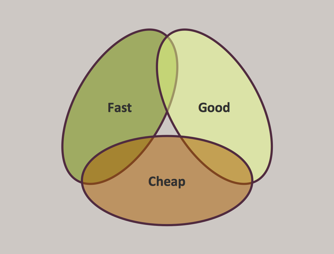
A Venn-diagram style chart of the "project triangle" showing visually the potential overlaps between speed, quality and low cost, along with the "inability" to accomplish all three.UML Use Case Diagram. Design Elements
UML Use Case Diagrams are used to illustrate the structure of arbitrarily complex systems and illustrates the service consumer - service provider relationship between components.
The vector stencils library "Analog and digital logic" contains 40 element symbols of logic (threshold) gates, bistable current switches, current controllers, regulators, electrical generators, and amplifiers.
Use it for drawing the digital and analog functions in electronic circuit diagrams and electrical schematics.
"Analogue electronics (or analog in American English) are electronic systems with a continuously variable signal, in contrast to digital electronics where signals usually take only two different levels. The term "analogue" describes the proportional relationship between a signal and a voltage or current that represents the signal." [Analogue electronics. Wikipedia]
"Digital electronics, or digital (electronic) circuits, represent signals by discrete bands of analog levels, rather than by a continuous range. All levels within a band represent the same signal state. Relatively small changes to the analog signal levels due to manufacturing tolerance, signal attenuation or parasitic noise do not leave the discrete envelope, and as a result are ignored by signal state sensing circuitry.
In most cases the number of these states is two, and they are represented by two voltage bands: one near a reference value (typically termed as "ground" or zero volts) and a value near the supply voltage, corresponding to the "false" ("0") and "true" ("1") values of the Boolean domain respectively.
Digital techniques are useful because it is easier to get an electronic device to switch into one of a number of known states than to accurately reproduce a continuous range of values.
Digital electronic circuits are usually made from large assemblies of logic gates, simple electronic representations of Boolean logic functions." [Digital electronics. Wikipedia]
The example "Design elements - Analog and digital logic" was drawn using the ConceptDraw PRO diagramming and vector drawing software extended with the Electrical Engineering solution from the Engineering area of ConceptDraw Solution Park.
Databases Access Objects Model with ConceptDraw DIAGRAM
ConceptDraw Basic gives the opportunity of interaction with any ODBC-compatible databases. For this the Database Access Objects Model is provided. All calls to the database are made by certain methods of objects of this model.Interior Design
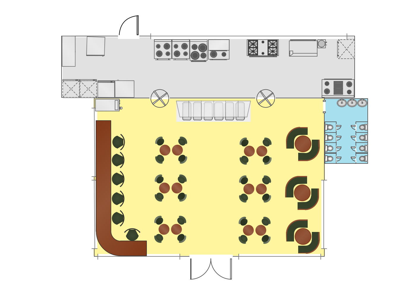
Interior design is simultaneously the science and art directed on beautification of interior space with the aim to provide convenience, comfort, aesthetic for pleasant staying of people. Interior design is very multifaceted, it includes the processes of interior design development, space planning, research, communication with project's stakeholders, programming, management, coordination, site inspections, all they are realized directly by interior designers or under its supervision. Creation of interior design project lets you plan and optimize the space, improve the navigation inside large premises, develop the decoration project according to the chosen style, create the lighting plan, ventilation scheme, plumbing and heating plans, and schematic of furniture arrangement. Numerous solutions from Building Plans area of ConceptDraw Solution Park contain examples, samples, templates and vector stencils libraries helpful for development the interior designs of different styles, for professional creation the interior design drawings and using them for technical documentation.- Data Flow Diagram (DFD) | Context Diagram Template | DFD Library ...
- Data Flow Diagram Level 0 1 2 For Library Management System
- Library Management System Level 0 Level 1
- Data Flow Diagram
- Cab booking public process - Collaboration BPMN 2.0 diagram ...
- Pyramid Diagram | Project triangle chart | Triangular chart template ...
- Pyramid Diagram | Project triangle chart | Triangle diagram template ...
- How To use Switches in Network Diagram | Cisco Switches and ...
- Network Gateway Router | Network Diagram Software Home Area ...
- Engineering | Electrical Drawing Software | Circuits and Logic ...
- Chart Of Triangles With Diagram
- UML activity diagram - Cash withdrawal from ATM | Data Flow ...
- Design elements - ERD (crow's foot notation) | Entity Relationship ...
- Element Of Electricity And Functions With Diagram
- Organizational culture - Triangle diagram | Pyramid Diagram ...
- Circuits and Logic Diagram Software | Electrical Drawing Software ...
- Bubble diagrams in Landscape Design with ConceptDraw PRO ...
- Design elements - Analog and digital logic | Engineering | Simple ...
- Affinity diagram - Business expansion | BPR Diagram . Business ...
- Pyramid Diagram | Pyramid Diagram | Project management triangle ...


