Tree Network Topology Diagram
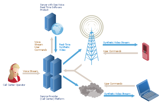
A Tree network topology (Hierarchical topology) is a hybrid network topology that contains the combination of two or more star networks connected via bus networks. Each star network is a LAN (local area network) with central computer or server and workstation nodes connected to it. The central computers of star networks are connected to a main cable that is called a bus. Each node of the Tree network can have an arbitrary number of child nodes, you can easy add/remove the separate workstations and even the whole star networks, the failure of one workstation will not affect the work of others. This topology is ideal solution when workstations are located in groups within a small physical region, rarely is used in WAN configurations. Computer and Networks solution from Computer and Networks area of ConceptDraw Solution Park contains templates, samples and numerous libraries of predesigned vector stencils of computer network devices and equipment, which can be effectively used for designing various network topologies diagrams, including Tree Network Topology."A call centre or call center is a centralised office used for the purpose of receiving or transmitting a large volume of requests by telephone. An inbound call centre is operated by a company to administer incoming product support or information inquiries from consumers. Outbound call centers are operated for telemarketing, solicitation of charitable or political donations, debt collection and market research. In addition to a call centre, collective handling of letter, fax, live support software,social media and e-mail at one location is known as a contact centre.
A call centre is operated through an extensive open workspace for call centre agents, with work stations that include a computer for each agent, a telephone set or headset connected to a telecom switch, and one or more supervisor stations. It can be independently operated or networked with additional centres, often linked to a corporate computer network, including mainframes, microcomputers and LANs. Increasingly, the voice and data pathways into the centre are linked through a set of new technologies called computer telephony integration (CTI)." [Call centre. Wikipedia]
This call center network diagram example was created using the ConceptDraw PRO diagramming and vector drawing software extended with the Telecommunication Network Diagrams solution from the Computer and Networks area of ConceptDraw Solution Park.
 Entity-Relationship Diagram (ERD)
An Entity-Relationship Diagram (ERD) is a visual presentation of entities and relationships. That type of diagrams is often used in the semi-structured or unstructured data in databases and information systems. At first glance ERD is similar to a flowch
- Linking Open Data Project
- Data Linked
- Data Flow Diagram Symbols. DFD Library | UML Diagram ...
- Sales Process Flowchart. Flowchart Examples | Data Flow Diagram ...
- Account Flowchart Stockbridge System. Flowchart Examples | Data ...
- Entity Relationship Diagram - ERD - Software for Design Crows Foot ...
- Wikipedia Flowchart
- Data Flow Diagram Symbols. DFD Library | Coad/Yourdon's Object ...
- Cross Functional Flowchart Wikipedia
- Difference Between Algorithm And Flowchart Wikipedia
- 4 Level pyramid model diagram - Information systems types ...
- Water Cycle Wiki
- Warehouse Layout Wikipedia
- Ivr Wikipedia
- Data Modeling Diagram | Data Modeling with Entity Relationship ...
- Call center network diagram | Call shop solution | How to do ...
- ERD Symbols and Meanings | Components of ER Diagram | Entity ...
- Process For Wiki Article
- Entity Relationship Diagram Examples | Components of ER Diagram ...

