"The symbols and conventions used in welding documentation are specified in national and international standards such as ISO 2553 Welded, brazed and soldered joints -- Symbolic representation on drawings and ISO 4063 Welding and allied processes -- Nomenclature of processes and reference numbers. The US standard symbols are outlined by the American National Standards Institute and the American Welding Society and are noted as "ANSI/ AWS".
In engineering drawings, each weld is conventionally identified by an arrow which points to the joint to be welded. The arrow is annotated with letters, numbers and symbols which indicate the exact specification of the weld. In complex applications, such as those involving alloys other than mild steel, more information may be called for than can comfortably be indicated using the symbols alone. Annotations are used in these cases." [Symbols and conventions used in welding documentation. Wikipedia]
The example chart "Elements of welding symbol" is redesigned using the ConceptDraw PRO diagramming and vector drawing software from the Wikipedia file: Elements of a welding symbol.PNG.
[en.wikipedia.org/ wiki/ File:Elements_ of_ a_ welding_ symbol.PNG]
The diagram example "Elements location of a welding symbol" is contained in the Mechanical Engineering solution from the Engineering area of ConceptDraw Solution Park.
Welding joint symbol chart

Entity Relationship Diagram Symbols

Flowchart design. Flowchart symbols, shapes, stencils and icons


Business Process Flowchart Symbols

Export from ConceptDraw DIAGRAM Document to a Graphic File


Data Flow Diagram Symbols. DFD Library

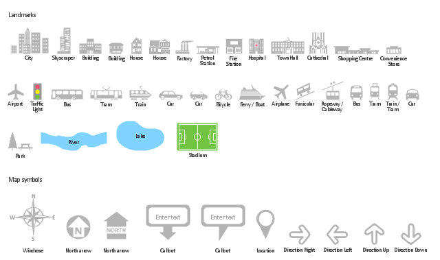
The vector stencils library "Landmarks" contains 34 signs and pictograms for drawing road and transit maps.
The vector stencils library "Map symbols" contains 10 signs and pictograms for drawing road and transit maps.
"A landmark is a recognizable natural or man-made feature used for navigation, a feature that stands out from its near environment and is often visible from long distances.
In modern use, the term can also be applied to smaller structures or features, that have become local or national symbols." [Landmark. Wikipedia]
The pictograms example "Design elements - Location map" was created using the ConceptDraw PRO diagramming and vector drawing software extended with the Spatial Infographics solution from the Maps area of ConceptDraw Solution Park.
Landmarks and Map symbols
Local area network (LAN). Computer and Network Examples
 diagram")

Basic Flowchart Symbols and Meaning


Spatial infographics Design Elements: Location Map
- Elements location of a welding symbol | Spatial infographics Design ...
- Elements location of a welding symbol | Sales arrows - Vector ...
- Elements location of a welding symbol | Elements location of a ...
- Arrow Symbols Png
- Cisco optical - Vector stencils library | Optical Splitter Icon Png
- Arrow Photoshop Png
- Elements location of a welding symbol | Welding symbols | Design ...
- Elements location of a welding symbol | Mechanical Drawing ...
- Elements location of a welding symbol | Design elements - Location ...
- Elements location of a welding symbol | Design elements - Welding ...